Supplying two loads for multiple boiler system
The Glitch & The Fix, May 2016

Glitch drawing: A multiple boiler system has been configured to supply two loads, with several piping errors. Graphics credit: John Siegenthaler, P.E.

Fix drawing 1: A pair of closely spaced tees is used to provide hydraulic separation between the boiler circulators and the load circulators. Graphics credit: John Siegenthaler, P.E.
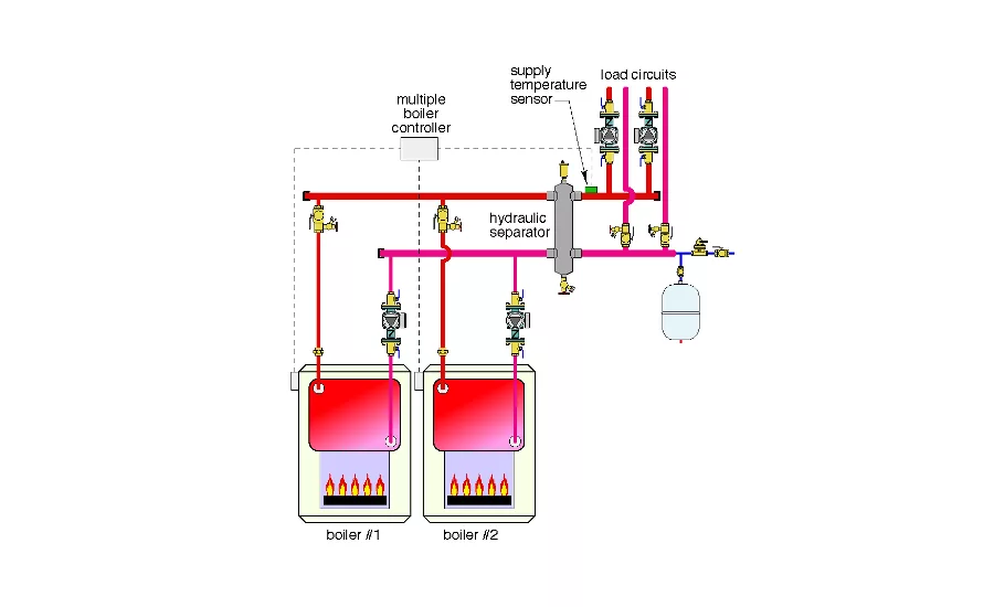
Fix drawing 2: A hydraulic separator is used to provide hydraulic separation between the boiler circulators and the load circulators. Graphics credit: John Siegenthaler, P.E.
The Glitch
A multiple boiler system has been configured to supply two loads as shown above.
There are several piping errors in this proposed design. Can you spot at least five of them?
The Fix
I’ve shown two solutions above. The first uses a pair of closely spaced tees to provide hydraulic separation between the boiler circulators and the load circulators (Fix Figure 1). The other uses a hydraulic separator (Fix Figure 2). Both are viable, and both provide the same supply water temperature to each load circuit, which would not be the case with the original system piping.
I prefer the solution using the hydraulic separator since that component not only replaces the closely spaced tees, it also replaces the high-efficiency air separator and provides dirt separation.
Here’s a summary of the other corrections:
1. Every boiler in a multiple boiler system should have its own circulator that only operates when that boiler is operating. The original schematic allows flow through all boilers regardless of which are firing.
2. It may seem simple to be sure the unions are installed between the boiler and the isolating valves, but I’ve seen it otherwise.
3. Always install the supply sensor for the staging controller on the distribution system-side of the hydraulic separation point (e.g., downstream of the closely spaced tees or downstream of the hydraulic separator).
4. Every secondary circuit should be equipped with purging valves to allow efficient filling and flushing.
5. Always locate secondary circulators so they pump into their associated circuit. With this arrangement, the primary loop becomes the pressure reference point and the pressure within the secondary circuit increases when the circulator is on.
Download a pdf of the May 2016 The Glitch & The Fix.
This article was originally published as "Supplying two loads" in the May 2016 issue of Plumbing & Mechanical.
Do you have a question or alternative solution to this month's Glitch & Fix? If so, please comment below!
Looking for a reprint of this article?
From high-res PDFs to custom plaques, order your copy today!