Wood-gasification boiler with existing piping
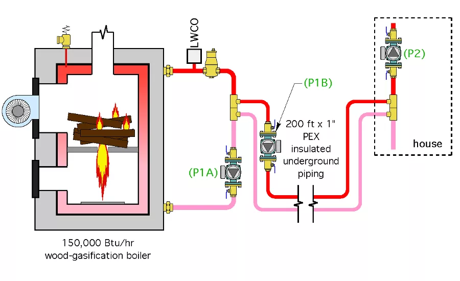
Glitch drawing: An installer plans to replace an outdoor wood-fired furnace with a new cordwood-gasification boiler using the existing underground piping. When the boiler is put into operation, its temperature quickly climbs to the high limit setting and the combustion fan turns off, leaving a large amount of wood to smolder in the combustion chamber. Graphics credit: John Siegenthaler, P.E.
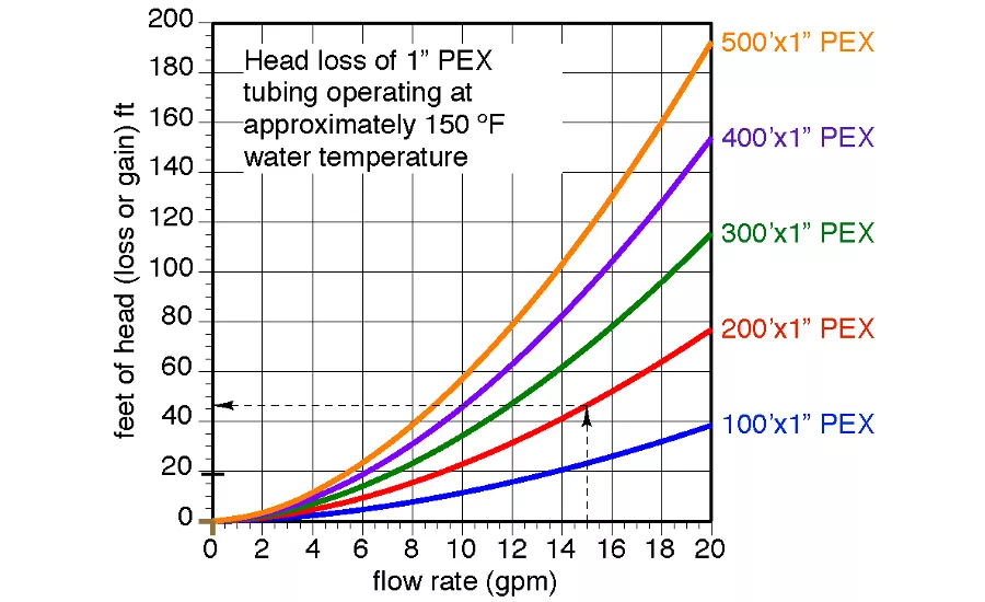
Fix drawing 1: The solution is easy for anyone who knows how to determine a circuit flow rate requirement, calculate the corresponding head loss of the circuit and use a pump curve. Graphics credit: John Siegenthaler, P.E.

Fix drawing 2: One can plot the pump curve for either a single larger circulator or perhaps two larger circulators connected in series, to find a circulator solution that will produce a flow of about 15 gpm at a corresponding head of about 46 ft. Graphics credit: John Siegenthaler, P.E.
The Glitch
Due to its low efficiency and high emissions, an installer plans to replace an outdoor wood-fired furnace with a new cordwood-gasification boiler with a rated output of 150,000 Btu/hr. The outdoor furnace is located about 100 ft. from the indoor mechanical room where the 1-in. PEX insulated underground piping joins the thermal storage tank. Due to existing landscaping, the installer plans to use the existing underground piping.
The new “near-boiler” piping is shown in The Glitch drawing above.
When the boiler is put into operation, its temperature quickly climbs to the high limit setting of 200° F and the combustion fan turns off, leaving a large amount of wood to smolder in the combustion chamber. All the circulators are nominal 1/25 hp and are running fine.
Can you determine why this is happening and propose a correction?
The Fix
The solution is easy for anyone who knows how to determine a circuit flow rate requirement, calculate the corresponding head loss of the circuit and use a pump curve.
If we assume the boiler needs to operate with a temperature gain of about 20° at full fire, the necessary water flow rate between the boiler and load is calculated as follows:
flow rate = (150,000Btu/hr.)/(500x20) = 15 gpm
The corresponding head loss of a 200-ft.-long circuit of 1-in. PEX at 15 gpm can be estimated from Fix drawing No. 1 above.
At 15 gpm flow rate, the head loss is about 46 ft.
Wow! Even those who select their circulators based on “what’s on the truck today” know that this is way beyond what a typical 1/25 hp circulator can produce. So the problem is simply not enough pump. The water “conveyor belt” isn’t moving heat away from the boiler at a rate even close to the rate at which heat is being produced. This is why the boiler temperature quickly climbs to the high limit setting.
The Second Fix
In two words: more pump!
One can plot the pump curve for either a single larger circulator or perhaps two larger circulators connected in series, to find a circulator solution that will produce a flow of about 15 gpm at a corresponding head of about 46 ft.
One pump curve, representing two 1/12 hp circulators connected in close-coupled series, is shown in Fix drawing No. 2 above.
Notice that the intersection of the pump curve and the head loss curve for the 200-ft.-long circuit of 1-in. PEX falls at about 14 gpm (shown by the yellow square). This is where the system would reach hydraulic equilibrium if this particular circulator selection is used.
That flow rate is a bit lower than the previously calculated “target” flow rate of 15 gpm. Still, assuming that it’s OK to operate the boiler with a slightly higher temperature rise (e.g., about 21.4° rather than 20°), this is an acceptable solution.
The take away: 1/25 hp circulators are great for the typical flow and head requirements of smaller zone circuits, but they just don’t cut it when trying to stay ahead of a 150,000 Btu/hr. boiler pumping through a relatively long (and, in my opinion, undersized) piping system.
Download a pdf of the April 2016 The Glitch & The Fix.
This was originally titled "Choke hold" in the April 2016 issue of Plumbing & Mechanical.
Looking for a reprint of this article?
From high-res PDFs to custom plaques, order your copy today!


