Piping for radiant panel heating
The Glitch and The Fix, May 2015
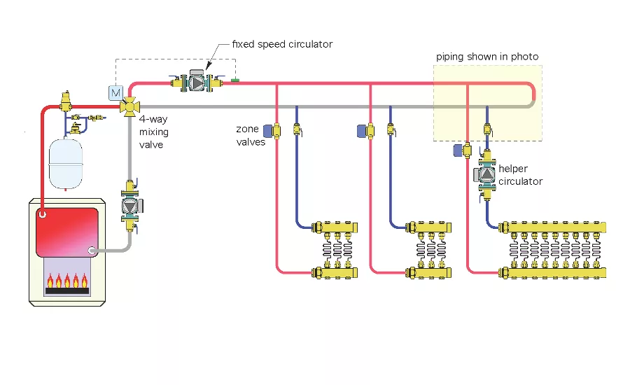
Glitch drawing 1: The radiant panel heating system is supplied by a low-flow-resistance, cast-iron boiler. Graphics credit: John Siegenthaler, P.E.
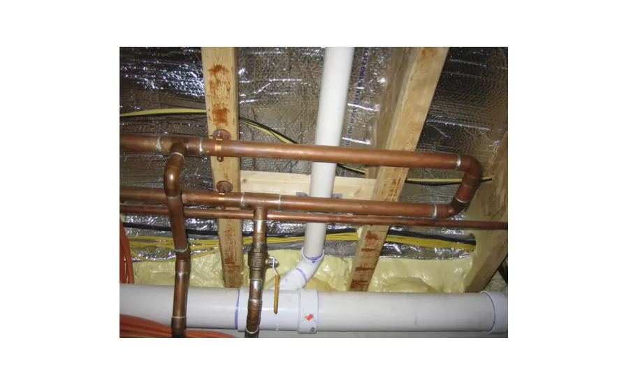
Glitch drawing 2: The piping here shows part of Glitch drawing 1. The piping to and from the two tees leads to a manifold station for radiant panel heating. One pipe is supply, the other is return. Photo credit: John Siegenthaler, P.E.
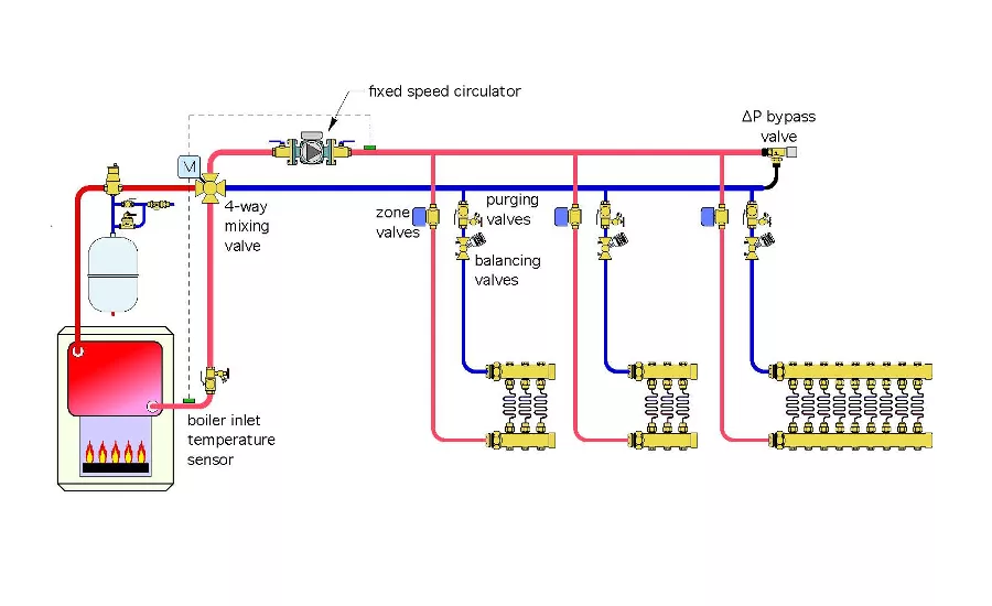
Fix drawing: Although the installer probably thought he had created a primary loop, the take-off for the manifold station is not a secondary circuit. Graphics credit: John Siegenthaler, P.E.
The Glitch
The piping in Glitch Image 2 shows part of the Glitch schematic (Glitch Image 1) above. The piping to and from the two tees leads to a manifold station for radiant panel heating. One pipe is supply, the other is return. There is a “helper” circulator farther down the wall. The piping strapped to the bottom of the floor joists is supposedly part of a primary loop. The system is supplied by a low flow-resistance, cast-iron boiler. Water temperature is controlled by a motorized four-way mixing valve.
Examine the photo and the schematic, and list several things that need to be corrected.
The Fix
Although the installer probably thought he had created a primary loop, and even though those two tees are relatively close to each other, the take-off for the manifold station is not a secondary circuit. Neither are the other two circuits that serve the smaller manifolds. If the tees aren’t right next to each other in the same pipe, it’s not a secondary circuit.
When the far right circuit with the helper pump is operating, there is likely to be some flow reversal through the closed end of the primary loop. When water gets pushed out the end of a circulator, all it cares about is getting back to the other end of that circulator.
The shortest path for this is around the closed end of the piping loop at the far right of the schematic and photo. This will cause unintentional mixing. It also will affect the differential pressure driving flow through the other two manifold stations. The pressure drop around the closed end of the loop is likely to be quite low and, thus, there may not be sufficient differential pressure to drive adequate flow through the other two manifold stations.
Other details that are missing or unnecessary include:
1. Boiler inlet water temperature sensor to the mixing valve controller, which helps prevent sustained flue gas condensation.
2. Purging valves on the return side of each manifold station circuit.
3. If the four-way mixing valve is close to the low flow-resistance boiler, there is no need of a circulator between this valve and the boiler.
One way to fix the system is shown in the Fix drawing above.
This assumes a fixed-speed circulator to drive flow through the three manifold stations. Thus, a differential pressure bypass valve is shown at the end of the headers. It should be set about 0.5 psi above the differential pressure needed when all three zone valves are open under design load conditions.
Another option, which wasn’t available when this system was installed, is a variable-speed, pressure-regulated circulator. If used, this circulator would eliminate the need of the differential pressure bypass valve. A savings that — today — would likely be greater than the additional cost of the variable-speed circulator.
Balancing valves have been added to each manifold subcircuit. These may not be necessary if the manifold stations have individual circuit-balancing valves.
A boiler inlet temperature sensor also has been added to ensure the boiler is not operating with sustained flue gas condensation.
If the system were installed today, three fixed-speed circulator could have been replaced by a single variable-speed, pressure-regulated circulator.
The problem that will develop here is flow.
Think of it this way. If you were water being moved along the primary loop by the primary circulator and you could decide if you would rather go through those long radiant panel circuits, as well as the piping to and from the manifold station, or simply zip around the end of the loop seen at the right side of the photo, which would you choose?
If you said you would rather take the short loop around the end, congratulations — you’re thinking like water!
Most (but not all) of the flow entering the tee just above the ball valve is just going to short-circuit around the end of this loop.
Looking for a reprint of this article?
From high-res PDFs to custom plaques, order your copy today!


