Twist, Turn & Tweak
John Siegenthaler
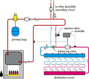
Piping schematics for both approaches are shown in Figures 1a and 1b. Notice that many of the piping details are similar in both systems. Closely spaced tees connect the injection risers to the primary loop. The injection risers drop down to create thermal traps that minimize off-cycle heat migration.
The two-way modulating valve acts as a metering device to regulate the rate of energy flow (heat) from the primary loop into the distribution circuit. It's like the carburetor on an engine admitting fuel as needed to meet the instantaneous system load.
A variable speed pump is more like a fuel injector than a carburetor. However, it also serves as a metering device for energy transfer from the hot primary loop to the lower temperature distribution circuit.

Don't Cramp Their Style
For either form of injection to deliver optimum performance, it must be "tuned" to the characteristics of both the heat source and the distribution system. The goal of this tuning is simple: When the system operates at full (design) load, the injection device should be "wide open."The plug of a two-way valve should be at its full open position. The motor of the injection pump should be operating at 100 percent speed.
I've looked at injection mixing systems where the balancing valve was installed correctly but left in its fully open position. The installer probably had no idea how to properly set it. The usual result is an underreving injection pump (on variable speed injection systems) or a two-way modulating valve with very little stem travel, which acts erratically under part load conditions.
Neither system uses the full operating range of its flow-controlling device. The accuracy of water temperature control, especially under part load conditions, suffers as a consequence. In some cases, the boiler also undergoes needless short cycling because the control calls for boiler firing based on the operating speed of the injection pump.
As injection mixing has grown in popularity, I've pondered how best to set the injection balancing valve to achieve full-range performance from the controlling device. There are several possible approaches. Some are based on classic valve theory. Others rely on thermodynamic principles. Some require more mathematics than others. Two of the three require specialized hardware. In my opinion, none of the methods seem obviously superior to the others. So I'll describe all three and let you decide which makes the most sense for your projects.

Cv Savvy
The first approach determines the necessary Cv value of the balancing valve so the injection control device is "wide open" under design load conditions. This method is useful only when a balancing valve with a Cv scale is installed in one of the injection risers.In case you've not heard of Cv value, it's simply the water flow rate in gallons per minute that produces in a 1 psi pressure drop across the (fully open) valve. The Cv value of valves designed for flow regulation usually is listed on product spec sheets and technical literature.
When a valve is partially closed, its Cv value decreases. This makes sense because the more restrictive the flow passage through the valve, the smaller the flow needed to produce a 1 psi pressure drop. Thus, any valve designed for flow regulation can be thought of as having a range of Cv values based on its stem position. Obviously the largest Cv value is when the valve's plug is fully open.
Here's the formula for determining the required Cv of the balancing valve in a system using a variable speed injection pump:
- Formula 1
where:
Cv = the required Cv setting of the balancing valve
fi = the calculated injection flow rate (in gpm)
Hp= the head of the injection pump at the injection flow rate (in feet) (read from pump curve)
r = 0.058 for 3/4-inch injection risers
r = 0.25 for 1/2-inch injection risers
To balance the injection risers, the installer simply sets the handle of the calibrated valve to the calculated Cv value. This is best done after the system is purged and the injection pump has had a few minutes of smooth, air-free operation at full speed.
If a two-way modulating valve is used as the injection device, it should be selected with a Cv value approximately equal to the design injection flow rate, which can be calculated using Formula 3. Never select an injection valve based solely on the size of the injection riser piping. The Cv value, not the pipe size, is what counts here.
The required Cv of the balancing valve for a system using a two-way injection valve can be found using Formula 2:
- Formula 2
where:
Cv bal. valve = Cv setting of the balancing valve
Fs = flow rate in the distribution system (in gpm)
fi = design injection flow rate (in gpm)
Cv inj. valve = Cv of selected injection valve
Just as with the variable speed system, purge the system of air, then adjust the Cv scale on balancing valve to this setting. You're done.
Going With The Flow: The second method involves calculating the system's design injection flow rate using Formula 3, then setting that flow using a flow meter in one of the injection risers (see Figure 2):
- Formula 3
where:
fi = required injection flow rate (in gpm)
load = required heat transfer to secondary circuit at design conditions (in Btu/hr.)
Ti = temperature of injection water from primary loop (in degrees F)
Tr = temperature of water returning from distribution circuit (in degrees F)
490 = a constant for water (use 479 for 30 percent glycol, 450 for 50 percent glycol)
A circuit setter valve with taps for connecting a manometer-type flow readout device would work, as would a small inline flow meter like those used on some radiant manifold systems. There are also devices available that combine a precision balancing valve with a small flow meter. They're ideal for such applications.
To balance the injection system, the installer runs the injection pump at 100 percent speed and closes the balancing valve as necessary to bring the injection flow rate to the calculated value. That's all there is to it. The injection risers are now balanced for both design and part load conditions and should not require any further adjustment.
You can also use this method with a two-way modulating injection valve. First make sure the two-way valve is fully open, then slowly close the balancing valve until the calculated injection flow rate is indicated on the flow meter.

Thermometry
The third balancing method again involves some simple calculations, but it relies on temperature measurements rather than Cv values or flow rates.Start by calculating the "target" temperature rise in the distribution loop under "current" conditions. Target refers to the temperature rise that will exist in the distribution system when the balancing valve is set properly and the injection pump is running at 100 percent speed. Current conditions refers to the temperatures present while adjusting the balancing valve.
For example, when you're setting the balancing valve, the current conditions may be 60-degree F water returning from the distribution system and 170-degree F water being injected from the primary loop. As the system warms up, both these temperatures probably will change. That's OK. The balancing valve can still be set using the current temperatures.
Here's the formula to use:
- Formula 4
where:
deltaT dist @ current = current (measured) temperature rise of distribution circuit (degrees F)
deltaT dist @ design = calculated temperature rise of distribution circuit at design load (degrees F)
deltaT inj @ current = current (measured) temperature difference between injection risers (degrees F)
deltaT inj @ design = calculated temperature difference between injection risers at design load (degrees F)
Keep in mind that the numbers associated with design load conditions in the above formula (15, 180 and 95) are fixed by your design and don't change during startup.
To use this method, you'll need a way to read three different temperatures almost simultaneously. Figure 3 shows where to take the readings. You could temporarily use snap-on thermometers or an infrared (gun-type) thermometer. Don't plan on rotating a single conventional thermometer from one piping location to another during this procedure. Such thermometers simply take too long to settle into a stable reading.
After purging, start the system with the injection pump at 100 percent speed and the balancing valve about 10 percent open. Let the system operate for a few minutes so the temperature of the water returning from the distribution system and the temperature of the hot water supplied from the primary loop can stabilize a bit.
Read the temperature of the incoming and existing injection risers, and then do the calculation for the target temperature rise of the distribution system. Check to see if the rise you measure is above or below this target value. If it's above, the injection flow rate is too high and the balancing valve should be closed slightly. If it's below, the target the balancing valve should be opened slightly.
Remember that the return water temperature and injection water temperature might change slightly while you make these measurements and calculations. If so, just recalculate the new target temperature rise and steer the system toward it with the balancing valve.
During a cold startup condition, there's always a temptation to adjust the balancing valve so water supplied to the distribution is up to its design temperature. Don't do this! It's not the supply temperature you're trying to set but rather the temperature rise of the distribution system. If you're starting with 60-degree F water returning from a cold slab, as in the above example, the supply temperature would only be 60+17.6 = 77.6 degrees F. This will not feel warm but is in fact the proper (current) condition for a balanced system. As the floor slab warms, the return water temperature will rise toward its normal value, as will the supply water temperature.
There you have it. Three ways to twist, turn and tweak those balancing valves so your injection mixing systems operate over their entire useful range. Use them and then watch your injection control operate at its full potential.
Looking for a reprint of this article?
From high-res PDFs to custom plaques, order your copy today!


