John Siegenthaler: The anatomy of a municipal pellet boiler system
A thousand words plus.

I’m sure everyone reading this column has heard the adage “a picture is worth a thousand words.” Although true, that statement is also a bit optimistic when it comes to describing some sophisticated hydronic heating systems.
Imagine trying to replace the schematic for heating system schematic in a commercial building with a narrative that’s limited to 1,000 words. To make it more challenging, imagine that the schematic embodies several innovative or non-traditional details, and that the description must be written for a reader who has a fundamental knowledge of modern hydronic systems.
Fortunately, the hydronic industry can rely on piping schematics to replace a lot of those words. There is no absolute standard for hydronic piping schematics. I’ve seen a wide variety of symbols used by different engineers, technicians and manufacturers. That’s not necessarily a bad thing provided that all the symbols are defined on a legend, and that the symbols are used consistently.
A case in point
The piping schematic in Figure 1 was developed to describe a floor heating system for a 13,000 square foot highway garage with a design heating load of 320,000 Btu/h. The primary heat source for this system is a 218,000 Btu/h pellet-fueled boiler. Although this boiler only supplies 68% of the design load, it will supply about 93% of the total seasonal space heating energy. What might be perceived as “undersizing” is actually quite beneficial in keeping the pellet boiler operating under favorable conditions for high efficiency and low emissions. Supplemental heat is provided by a pair of propane-fueled modulating/condensing boilers. These are some of the major elements in Figure 1.
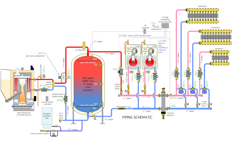
Another element that immediately draws attention is the 500 gallon ASME-certified thermal storage tank. A tank this size is certainly a departure from a normal multiple boiler system. It’s necessary to allow the pellet boiler to operate for multiple hour burn cycles and thus at or very close to steady state efficiency. Pellet-fueled boilers should not be tuned on and off based on heating demands from space heating thermostats, as is commonplace with fossil-fuel boilers. A thermal storage tank sized for approximately 2 gallons of water storage per 1000 Btu/h of rated pellet boiler capacity allows for long burn cycles.
The pellet boiler is turned on and off based on the temperature at two sensors in the thermal storage tank. The “go” signal occurs when the temperature at sensor (TS2) in the upper portion of the tank drops to some minimum temperature. The value of that minimum temperature could be a fixed setpoint, or it could be determined based on outdoor reset control. The latter is used in this system. It provides the advantage of allowing the thermal storage tank to cool to the lowest possible temperature, at which it can still supply the building’s current heating load before calling for the pellet boiler to operate. In the case of a heated bare slab in a garage facility, that temperature will be quite low, perhaps 95° F to 100° F on a design day, and even lower during partial load conditions. The lower the tank temperature can be before the pellet boiler is referred, the longer the ensuing burn cycle.
Once turned on. the pellet boiler continues to fire until the temperature at the lower tank sensor (TS4) reaches some high limit, which is typically in the range of 170° to 180°. This control technique is called temperature stacking. It helps ensure a long burn cycle and leaves the thermal storage tank fully charged with heat so it can supply the load for several hours while the pellet boiler is off.
Several other components are seen between the pellet boiler and thermal storage tank. There are two circulators, (P1A) and (P1B). (P1A) is a constant speed circulator that maintains a fixed flow rate through the boiler whenever it is operating. (P1B) is a variable speed circulator that responds to the temperature at the boiler inlet. When this temperature is below 130°, (P1B) is off. This prevents all but a trickle of flow between the boiler and thermal storage tank — thanks to the uncoupling effect of the closely spaced tees. As the temperature at the boiler inlet climbs above 130°, (P1B) speeds up, allowing a greater rate of heat transfer away from the boiler. When the boiler inlet temperature is 135° or higher, (P1B) is operating at full speed. This control action prevents sustained flue gas condensation within the pellet boiler.
The motorized ball valve (MBV1) opens whenever the pellet boiler is operating and closes at all other times. This prevents any forward or reverse heat migration between the pellet boiler and thermal storage tank. Without this valve, forward heat migration would develop due to a very slight (but non-zero) pressure drops across the thermal storage tank cause by operation of the circulators on the right side of the tank. Reverse heat migration would occur when the pellet boiler is off and has cooled down. Under this condition, the buoyancy of the hot water in thermal storage would create a slow, but persistent flow backward through the boiler if that flow path was not blocked.
The normally open zone valve (ZV1) remains closed whenever line voltage is available to the system. Its sole purpose is to open during a power outage, which allows forward thermosiphoning between the pellet boiler and thermal storage tank. The thermosiphon flow dissipates residual heat caused by pellets that are still burning inside the boiler.
Tank trivia
Although it appears to be a very simple element in this system, the thermal storage tank embodies a number of important details. It is piped in a “2-pipe” configuration, which allows the possibility of hot water flow from the pellet boiler directly to the load, rather than having to first pass through the tank.
This can speed up recovery from a setback condition, especially if the water in the tank has cooled substantially.
The tank also has upper and lower baffle plates that prevent entering vertical flow jets from disrupting temperature stratification. Preserving stratification preserves the “exergy” or usability of heat from the tank relative to a tank that is fully mixed. The circular baffles have a diameter that is six inches less than the tank’s inside diameter. Flow through the resulting 3-inch wide annular spaces is at a very low velocity.
The steel tank shell is covered with a monolithic layer of 4-inch spray polyurethane foam, giving it an R-value of 24° F•hr•ft2/Btu. The foam insulation is then covered with an intumescent coating, which provides a thermal barrier in the event of a fire.
Because the pressure drop associated with flow within the tank is extremely low, the tank provides hydraulic separation between the circulators associated with the pellet boiler, and those on the right (load) side of the tank.
Variable speed injection
Hot water from the top of the thermal storage tank is passed to the load by a variable speed injection circulator (P3). This serves as a fixed first stage heat input to the load. The speed of this circulator is controlled by a 0-10 VDC signal from the multiple boiler controller. The objective is to modulate the circulator speed as necessary to achieve a calculated target supply water temperature at sensor (S2). The target temperature is continuously calculated based on outdoor reset logic. Sensor (S2) is mounted on the outlet side of the hydraulic separator so that it detects the fully mixed supply water temperature.
The variable speed circulator (P3) is only allowed to operate when the temperature at the top of the thermal storage tank, measured at sensor (S3) is at least 5° above the temperature on the return side of the loads, measured at sensor (S4). If (P3) is operating, and the temperature at sensor (S3) drops to 3° or less above the temperature at sensor (S4), circulator (P3) is turned off. This important detail allows the thermal storage tank to contribute heat to the system while the mod/con boilers are operating, but also prevents heat generated by the mod/con boilers from being inadvertently sent into thermal storage. This control logic is executed by a simple differential temperature controller. It could also be implemented as a few lines of code within a building automation system.
If the variable speed injection pump cannot maintain the necessary target supply water temperature to the load, one or both of the mod/con boilers is operated. Each of these boilers is modulated through a 5:1 turndown ratio by 0-10 VDC control signals from the boiler controller. This allows for a 10:1 turndown ratio to the load. If ever necessary, the two mod/con boilers, each rated for 185,000 Btu/h output, can supply the building’s design heating load.
End of the line
The load consists of three independently controlled zones of slab heating. Circulators (P4), (P5) and (P6) operate continuously during the heating season. This helps to provide more uniform floor surface temperatures, especially near the large overhead doors in a garage-type building. When a zone calls for heat, a motorized 3-way diverter valve is powered on to route flow from the supply header into the zone. When a zone is operating, all flow returning from the floor circuits passes to the return header. The diverter valves are not to be confused with mixing valves. Mixing is not necessary since the supply water temperature is fully controlled by the three modulating stages of heat input.
A hydraulic separator in combination with short and generously sized headers isolates the pressure dynamics of all circulators connected to the headers. It also provides high efficiency air, dirt and magnetic particle separation.
The piping schematic in Figure 1 also contains more “routine” details, such as a purging valve on each load circuit, located just upstream of the return header. There are also spring-loaded check valves on all three heat inputs at the left side of the hydraulic separator. These valves prevent flow reversal through inactive heat input circuits. A large expansion tank is needed because of the large system volume. An automatic make up water system is also shown.
Putting it all together
This collection of components and details forms a smoothly operating system with pellet-supplied heat as the priority, but with fully automatic supplemental and backup input from the two mod/cons. This system takes advantage of modern piping and control concepts, yet uses readily available and easily serviced hardware. This design concept is also easily scalable for larger or smaller load situations. Perhaps you can use it, in part or in whole, for an upcoming biomass heating system.
Finally, in case you’re wondering, I used 1,530 words to describe the picture in Figure 1. A thousand words just weren’t enough.
Looking for a reprint of this article?
From high-res PDFs to custom plaques, order your copy today!


