John Siegenthaler: Extended manifold systems
Less tubing, less drilling, less fastening.
Lead image courtesy of Inok / iStock / Getty Images Plus.
Several years ago, I had the opportunity of visiting the Mostra Convegno Expocomfort show in Milan, Italy. It ranks right up there with the famous ISH show in Frankfurt, Germany, as a “bucket list” event for those who are passionate about hydronic heating and plumbing.
After spending a couple of days walking the show, one of the folks at the huge Caleffi booth asked me; “What are your impressions of Mostra?” I gave a rather off-the-cuff response: “Does the world really need more manifold systems?”
There were dozens upon dozens of manifold offerings. They were made of copper, brass, stainless steel, polypropylene and other engineered polymers. Some had balancing valves, along with trim such as isolation valves, air vents, fill/drain provisions, temperature gauges, electric valve actuators and spaces for labeling each circuit. Some manifold station systems even included circulators, mixing valves, insulation shells and provisions for hydraulic separation.
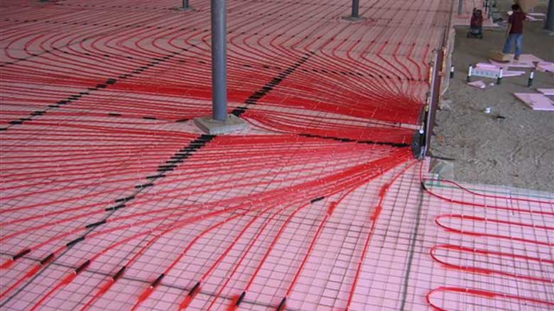
Much of this technology is now available in North America, with dozens of suppliers and a wide range of options. Manifold stations, in some sense, have become a commodity in the global hydronics market. They are most widely used in radiant panel systems for heated floors, walls and ceilings. It’s common to see manifold stations that can accommodate two to 12 individual circuits. These circuits are typically “gathered” together as they approach the location of the manifold station, as shown in Figure 1.
FIGURE 1
Stretching the concept
Fundamentally, all manifold systems are just a way to divide an entering flow in multiple parallel paths. This provides the same supply water temperature to each path. It also allows for individual circuit flow adjustments. The latter is “enhanced” by the fact that head loss along the length of a typical short and larger diameter manifold is very small relative to the head loss through individual parallel circuits.
There are situations where a classic manifold station collecting multiple parallel circuits, although possible, may not be the best option. One example is a homerun distribution system serving many panel radiators that are spread out over a relatively large building. In theory, each radiator could be supplied and returned to a single manifold station, but doing so would probably require several hundred feet of small (3/8-inch or 1/2-inch PEX, PE-RT or PEX-AL-PEX) tubing, along with many holes drilled through framing, clips where the tubing runs along the framing and possibly hundreds of feet of insulation if some of the tubing is routed through unconditioned space. Insulated or not, all this piping emits heat into spaces that are not where the radiators being served are located.
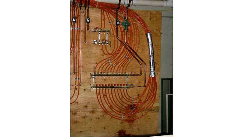
The goal is to get the heated water from the manifold station to each of the heat emitters being served with minimal amounts of materials and labor. Poorly planned or located manifold stations, such as the one shown in Figure 2, can “waste” a lot of tubing.
FIGURE 2
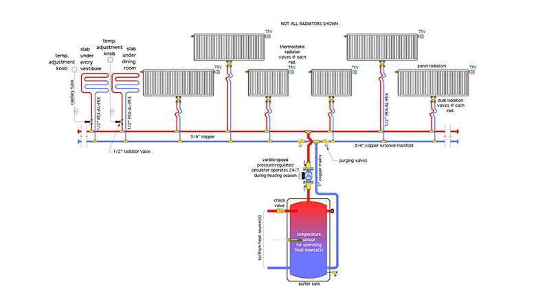
An alternate approach is what I call an extended manifold. It’s basically two straight runs of rigid piping with several tees located as close as possible to where the flexible tubing circuits begin and end. Figure 3 shows the concept for one extended manifold that serves several panel radiators and two floor heating circuits.
FIGURE 3
 [Click image to enlarge]
This assembly is for a house with a design heating load of 36,000 Btu/h. In total, it serves 10 panel radiators and two small floor heating circuits. Flow through each of the 12 parallel circuits is regulated by thermostatic radiator valves. Ten of the thermostatic valve operators are mounted directly to integral valves on the panel radiators. The two floor heating circuits use a valve mounted in an accessible location and connected to a wall-mounted adjustment knob via a capillary tube. Heat output from each of the 12 circuits can be individually adjusted.
A small variable-speed pressure-regulated circulator operates 24/7 during the heating season. Its speed automatically increases or decreases as the flow requirements of the heat emitters change.
The extended manifold consists of two runs (supply and return) of 3/4” copper tubing. Each branch connection is made using a 3/4-inch x 3/4-inch x 1/2-inch tee (sweat or press). The 1/2-inch side port on each tee transitions to a 1/2-inch PEX-AL-PEX compression fitting. Figure 4 shows the fittings at one of these “take-off” points.
FIGURE 4
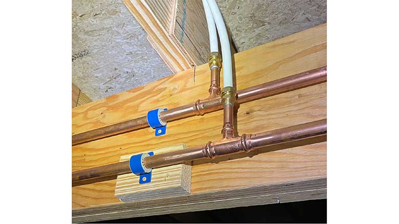 A close-up of a 3/4 x 3/4 x 1/2 tee going to 1/2" PEX-AL-PEX.
The project in which this distribution system was installed had a 12-inch deep laminated veneer lumber (LVL) main girder running the length of the building to support the floor joists. The 3/4-inch tubing that forms the extended manifold just runs straight along this girder. After pressure testing the copper tubing was covered with 1/2-inch thick elastomeric foam insulation.
You’ll notice some short stubs of 1/2-inch copper that are soldered to the brass adapters connected to the 1/2-inch PEX-AL-PEX tubing. This was done because there was no source for 1/2-inch PEX-AL-PEX x 1/2-inch FTG adapters, which, if available, could have been directly pressed to the 1/2-inch side ports on the tees.
The total flow rate to the extended manifold, at design load conditions, is only about 4 gpm. So each 3/4-inch tube is only operating at approximately 2 gpm (assuming the mains tie in at the midway point between all the heat emitters, and with all heat emitters operating).
Because the extended manifold piping was insulated there was very little temperature drop from where the mains connect, to the outer end of each 3/4-inch tube. Thus, each heat emitter receives water at about the same temperature.
Individual flow adjustments (e.g., balancing) can be done at each of the radiator valves.
The buffer tank allows the “micro-zoned” distribution system to operate without short-cycling the heat source. This project used an air-to-water heat pump as the primary heat source, but it could just as easily be a boiler or a combination of a heat pump and a boiler.
The control logic is simple: operate the heat source(s) as necessary to maintain some specified temperature range in the buffer tank. It could be a setpoint range such as 100°-120°F, or based on outdoor reset control. The latter will typically improve the performance of heat pumps as well as mod/con boilers.
Extended manifolds trade a few feet of rigid piping (typically type M copper) for many more feet of 1/2-inch flexible tubing (PEX, PERT, or PEX-AL-PEX) along with a manifold station to connect all that flexible tubing. They typically reduce the amount of drilling and fastening needed to install that flexible tubing through or onto the building’s framing. They represent an alternative to “classic” homerun distribution systems, where all circuits begin and end at a single compact manifold station. Keep them in mind when the right building layout comes along.
Looking for a reprint of this article?
From high-res PDFs to custom plaques, order your copy today!


