John Siegenthaler: Eyes for a heat pump
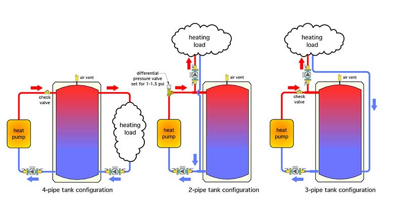
Buffer tanks are necessary for heavily zoned distribution systems.
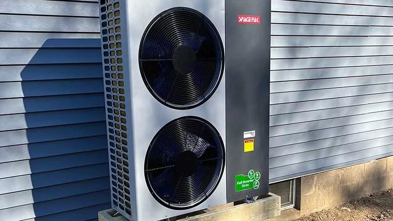
Image courtesy of tchara / iStock / Getty Images Plus.
More and more hydronic heating and cooling systems are being designed around air-to-water and water-to-water (geothermal) heat pumps. When the heating distribution system is extensively zoned, a buffer tank is typically installed between the heat pump and that distribution system.
One reason it’s there is to prevent the heat pump from short cycling when the active heating load is significantly smaller than the heat pump’s output. A buffer tank, piped in either a “2-pipe,” “3-pipe” or “4-pipe” configuration, as shown in Figure 1, also provides hydraulic separation between the heat pump and the distribution circulators, allowing the heat pump to operate at an adequate flow rate (typically 2-3 gpm /12,000 Btu/h of heating capacity) regardless of the flow rate through the distribution system.
 [CLICK IMAGE TO ENLARGE]
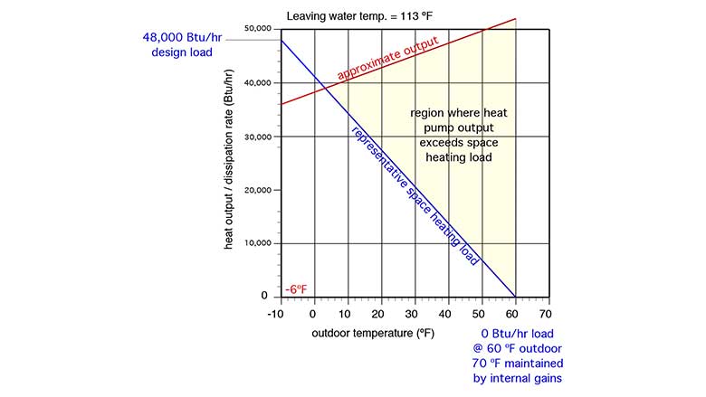
The buffer tank is critically important when a single-speed “on/off” heat pump is used. Figure 2 shows a typical relationship between the space heating load of a building having a design load of 48,000 Btu/h at -10° F outdoor temperature, and a nominal 4-ton rated air-to-water heat pump.
 [CLICK IMAGE TO ENLARGE]
The yellow shaded area represents conditions where the heat pump’s output exceeds the load. This is where a buffer tank comes into action. It absorbs the difference between the rate of heat output by the heat pump and the rate of heat dissipation by the heat emitters.
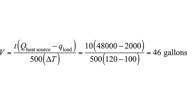
The size of a buffer tank is based on two parameters the designer chooses:
- What is the minimum run time of the heat pump that avoids their definition of “short cycle?”
- What is the allow temperature change of the buffer tank during the minimum on-cycle time?
Once these two decisions are made, the math is pretty easy. The minimum buffer tank size can be determined using Formula 1.
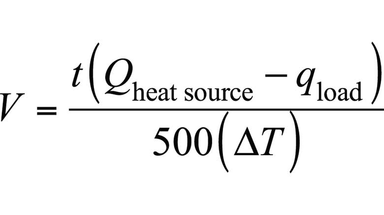
Where:
V = required volume of the buffer tank (gallons);
t = desired duration of the heat source’s “on cycle” (minutes);
Qheat source = heat output rate of the heat source (Btu/h);
qload = rate of heat extraction from the tank (can be zero) (Btu/h); and
∆T = temperature rise of the tank from when the heat source is turned on to when it is turned off (° F)
Here’s an example. A designer wants a hydronic heat pump with a rated output of 48,000 Btu/h to operate with a minimum on-cycle of 10 minutes while supplying heat to a towel warmer radiator releasing heat at 2000 Btu/h. The heat pump responds to the buffer tank temperature. It turns on when the buffer tank temperature drops to 100° F, and off when the tank reaches 120° F. What is the necessary tank buffer tank volume to accomplish this?
Just put the numbers into the formula and grab a calculator
Larger buffer tanks can provide longer heat source on-cycles. They can also allow a narrower temperature change over a specific on-cycle. It’s easy to evaluate the trade-offs between on-cycle length and tank temperature swing using Formula 1. Large buffer tanks obviously cost more, take up more room in a mechanical room and usually have higher standby heat loss.
Keep in mind that the value of qload can be zero. This would be the case, at times, if the heat pump is turned on and off solely based on the buffer tank temperature (rather than based on any signal from the load, such as a thermostat call. Treating qload = 0 is a conservative way to size the buffer tank.
Tell me what to do
When a system is set up with a buffer tank, it’s important to think about how the heat pump will be controlled. For example, in systems with a 2-pipe or 3-pipe tank piping configuration, it’s possible for the heat pump flow rate and the load flow rate to be very close, or even equal. Such a situation would greatly reduce any flow through the tank. If the two flow rates were equal, the flow rate through the tank would be zero. Under such conditions the thermal mass of the tank is not being “engaged” and the tank is essentially just an expensive wide spot in the piping. As such it offers little more than hydraulic separation of the heat pump and load circulators.
This scenario can be prevented by turning the heat pump on and off based solely on the temperature in the buffer tank. That temperature could be measured by a sensor mounted in a well at the mid-height of the tank. An example of the control logic would be:
Heat pump = ON if Tsensor ≤ 105° F, and
Heat pump = OFF if Tsensor ≥ 120° F.
This control concept “tells” the heat pump that its sole “responsibility” is to maintain the temperature at the tank sensor between 105° and 120° F. There’s no need to “look” at what’s happening with zone thermostats. The tank temperature becomes a proxy for the load. If the load is high, the tank temperature will drop quickly and the heat pump will operate more frequently to keep the tank within the assigned temperature range. When all the zones are satisfied and the flow in the distribution system drops to zero, the heat pump may continue to run until the tank is charged back up to the upper-temperature setting. Assuming that heat loss from the tank is minimal, hot water is ready to immediately flow to the load when a zone calls for heat.
Double duty
One of the “ancillary” benefits of having a buffer tank in the system is its ability to act as a domestic water heater, or preheater, depending on the DHW delivery temperature required.
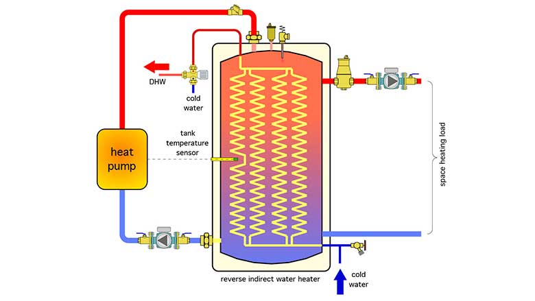
One approach uses a “reverse indirect” water heater for the buffer tank, as shown in Figure 3.
 [CLICK IMAGE TO ENLARGE]
The heat pump simply maintains the temperature at the tank sensor between some high and low limit setting, such as 105° up to 115° F. Cold domestic water is heated as it passes through the internal coils whenever hot water is drawn from a fixture.
If the DHW delivery temperature requirement is higher than what can be achieved as the water passes through the coils, the preheated water can be routed to a tank-type or instantaneous water heater for the final temperature boost.
Since the tank temperature is being maintained for domestic water heating purposes, there’s always hot water ready to flow to the space heating load. It’s also possible to prioritize the domestic water heating function by temporarily stopping flow to space heating if the buffer tank temperature dropped to some specified lower limit.
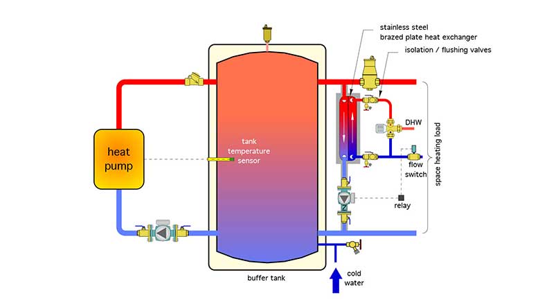
Another option is to use an external stainless steel brazed plate heat exchanger as shown in figure 4.
 [CLICK IMAGE TO ENLARGE]
A flow switch detects any hot water flow to a fixture greater than 0.5 to 0.7 gpm. It signals a relay to turn on the circulator below the heat exchanger. Hot water from the upper portion of the buffer tank flows through the primary side of the heat exchanger. It passes heat to the domestic water, moving in counterflow, through the other side of the heat exchanger. An anti-scald mixing valve is shown. However, if the domestic water leaving the heat exchanger needs a final temperature boost it would be routed to a tank-type or instantaneous water heater, and then through the anti-scald valve.
Combination isolation/flushing valves on each of the domestic water connections to the heat exchanger allow for a mild acid washing if necessary to remove scale.
All piping and components in the DHW subassembly should be insulated to minimize heat loss.
Change of pace
You may be wondering if all this applies to systems using variable-speed air-to-water or water-to-water heat pumps. It does, but with a few nuances that we’ll get into that in next month’s Hydronics Workshop column.
Looking for a reprint of this article?
From high-res PDFs to custom plaques, order your copy today!


