John Siegenthaler: Adding a heat pump
Several possible approaches.

Image courtesy of welcomia / iStock / Getty Images Plus
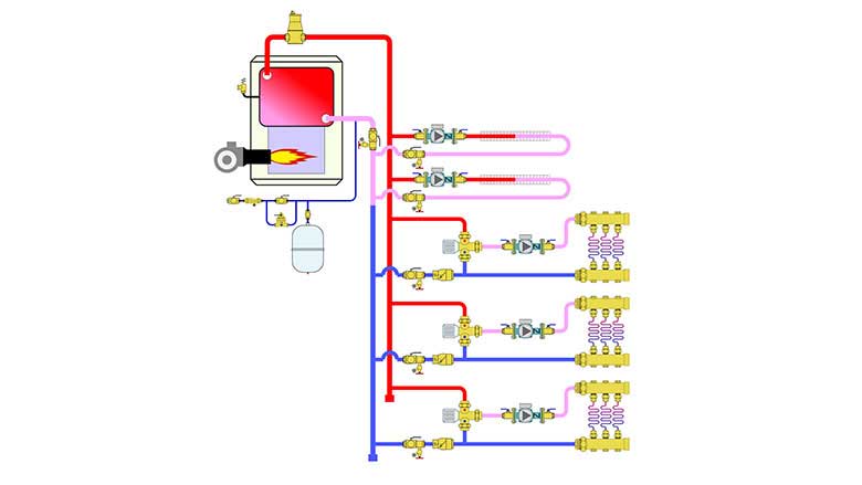
Many legacy hydronic heating systems use a fossil fuel boiler to supply fin-tube baseboard heat emitters in some areas of a building and lower-temperature radiant panels in other areas. The boilers in these systems are typically set up to supply high water temperatures in the range of 180° to 200° F for the baseboard. One or more mixing valves are used to create lower water temperatures for the radiant panel circuits. Figure 1 shows an example of such a system with two high-temperature and three lower-temperature zones.
These configurations can pose a challenge when it’s time to add a hydronic heat pump (e.g., air-to-water or geothermal water-to-water). The goal is usually to shift as much of the seasonal heating energy requirement as possible away from fossil fuel and to the electrically powered heat pump.
The lower-temperature radiant circuits can usually be directly supplied from the heat pump, but the higher water temperatures required for the baseboard under design load conditions are out of the range of nearly all currently available water-to-water or air-to-water heat pumps.
There are several ways to approach this situation:
- Scrap the existing boiler and existing high-temperature heat emitters in favor of a new lower-temperature system that can be completely supplied by the heat pump;
- Add heat emitters to the high-temperature zones to lower the required supply water temperatures into a range suitable for the heat pump; or
- Improve the thermal efficiency of the building envelope to lower the required supply water temperatures into a range suitable for the heat pump.
While there are circumstances where each of the above options can be used based on customer preferences, ability to access existing piping, available wall space, cost of envelope improvements, etc., there’s also another option: Retain the existing boiler and its associated high-temperature distribution system, but use the heat pump — whenever possible as the “preferred” heat source for all portions of the system.
This approach has several benefits including:
- The existing boiler can serve as both supplemental and backup heat source if the heat pump was down for service, or if the heat pump capacity was insufficient to meet the load under very low outdoor temperatures;
- It doesn't require significant changes to the portion of the system within living spaces (e.g., placement of new heat emitters and associated piping);
- It doesn't require the disruption or cost associated with changes to the thermal envelope;
- Use of the existing boiler could potentially be coordinated with time-of-use electrical rates to avoid periods of high electrical cost or demand charges;
- The boiler could be used for a thermal sterilization cycle of the domestic hot water portion of the system to protect against Legionella;
- It’s lower in cost compared to scrapping the entire existing system; and
- During a power outage most residential boilers running on gas or oil can be operated by a small (2KW or less) emergency generator.
Putting it together
Figure 2 shows one system configuration that retains an existing boiler and its associated high-temperature distribution system while adding a heat pump.
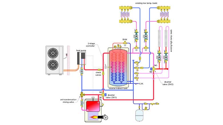
The outlet of the existing boiler is piped to a diverter valve (DV1), which is equipped with a spring return actuator. When (DV1) is “unpowered,” flow leaving the boiler goes through the valve’s normally open (NO) port into the upper left connection of the reverse indirect tank. When (DV1) is “powered,” flow exiting the boiler goes to a second diverter valve (DV2). We’ll get to what that second valve is for shortly.
The conventional boiler is protected against sustained flue gas condensation by a thermostatic mixing (“anti-condensation”) valve. This enables the boiler to maintain the buffer tank at relatively low temperatures — when appropriate — without the corrosion issues associated with flue gas condensation. It blends hot water leaving the boiler with cool return water so that the mixed temperature entering the boiler is at or above 130° F. It’s an important detail that, if neglected, can quickly destroy a conventional boiler and it’s venting system.
The reverse indirect tank serves three functions. First, it acts as a buffer tank for the heat pump or the boiler. This is especially important when the distribution system is zoned and a single-stage (non-inverter) heat pump is used. Second, it provides domestic water heating through the internal coil heat exchangers. Finally, the very low head loss through the tank provides a good degree of hydraulic separation for the load and heat source circulators.
If the tank temperature is maintained high enough for most residential DHW requirements (nominal 120° F), the domestic water leaving the internal coils should be hot enough for delivery to fixtures. If the tank temperature is maintained based on outdoor reset control, which definitely improves heat pump performance, the water leaving the coils will need a temperature boost. The latter can be supplied by several means including — perhaps — an existing indirect water heater supplied by the boiler. Other options include tank-type or tankless electric water heaters. In either case, the goal is for the heat pump to supply the majority of the energy required for the DHW load.
Another possibility is to use the boiler to provide a daily thermal sterilization cycle in which the tank temperature is raised to minimum of 140° F for 30 minutes to kill Legionella bacteria. The mixing valves on the lower-temperature circuits limit water temperature to the radiant panels during this sterilization cycle.
A 2-stage controller (setpoint or outdoor reset) operates the heat pump as a fixed first-stage heat source. The boiler is treated as a fixed second-stage heat source.
The goal is to supply all heat emitters from the heat pump whenever possible, and only call on the boiler when necessary.
Keep in mind that there are many hours in a heating season when the water temperature supplied to the baseboard can be far lower than the “design load” value, and thus within the range of the heat pump. For example, simulation of a nominal 4-ton low-ambient air-to-water heat pump supplying a building with a design load of 40,000 Btu/h in Syracuse, New York, that has a fin-tube baseboard system with a design load supply temperature requirement of 180° F and employs outdoor reset control, indicates that the heat pump can supply about 89% of the seasonal space heating energy. The takeaways: Don’t give up on baseboard when it comes to a heat pump and incorporate outdoor reset in any such application.
Heat pump helper
If the heat pump can’t maintain the required tank temperature, the controller enables boiler operation. There should be a time delay of at least 3 minutes between activation of stage 1 and stage 2. This allows the heat pump to stabilize its heat output and reveal if it can create a sufficient increasing temperature trend in the tank before calling on the boiler. There’s no point in firing the boiler only to turn it off one minute later.
During very cold weather, when the baseboard requires water temperatures above what the heat pump can supply, both diverter valves (DV1 & DV2) are powered on. Heated water from the boiler goes directly to the high-temperature load circuits, but not to the lower-temperature circuits, which are still supplied from the heat pump.
Toggle time
If, during this very cold weather, the boiler is also needed for supplemental heating of the tank, some type of priority control strategy is needed that can operate the diverter valve (DV1) to “toggle” heat delivery between the tank and the baseboard circuits.
One approach is to “toggle” heat output from the boiler between the two loads, but limit the duration of heat delivery to each of them to say 10 minutes using a repeat cycle time delay relay. For example, assume a baseboard zone calls for heat. If that zone, or perhaps another baseboard zone is still calling after 10 minutes from when the call began, and if stage 2 of the tank temperature controller is calling for heat, and if it’s below some outdoor temperature where the heat pump cannot create the supply water temperature needed by the higher temperature zones, then the repeat cycle time delay relay would switch DV1 to route boiler flow to the tank for the next 10 minutes. After that 10 minutes, the same logic cycle would repeat. This would allocate heat to both high- and low-temperature space heating as well as maintain the tank temperature for domestic water heating. Figure 3 shows a ladder diagram with the necessary hard-wired logic.
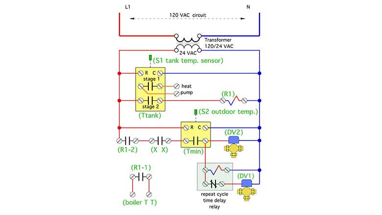
Figure 4 shows one example of a repeat cycle time delay relay.

Image courtesy of Allied Electronics.
These industrial-grade relays, which mount to standard 8-pin octal sockets, sell for around $50. Most have adjustable on and off times, which would allow the time over which heat flows from the boiler to the tank to be different from when heat flows to the high temperature baseboard. For example, if the load represented by the tank was twice the load of the baseboard, the “off time” for diverter valve (DV1) could be twice the “on time.”
(Ttank) is the 2-stage temperature controller monitoring tank temperature. (Tmin) is a temperature controller measuring the outdoor air temperature. Its normally open contacts close at an outdoor temperature where the heat pump can no longer supply the necessary water temperature to the higher temperature zones. (X X) is a relay contact found in most multi-zone relay centers, that would close whenever one or more of the high-temperature (but not low-temperature) zones calls for heat.
Why not just…
I suspect some readers are thinking — why not just let the boiler heat the tank to the higher temperature required by the baseboards under design load conditions? After all, the thermostatic mixing valves on the radiant circuit can blend those temperatures back down, and the mixing valve on the DHW tank can also protect against scalding.
The answer comes from the underlying goal — to supply as much of the heating energy as possible from the heat pump. If the tank is allowed to climb over above a nominal 125° F, the COP of the heat pump diminishes quickly. At some point, the tank would be hot enough to preclude operating the heat pump based on the limitation of its refrigerant cycle.
Alternatives exist
I’m sure there are other possible control approaches — such as the use of two-stage thermostats in each high-temperature zone, which could eliminate the need for outdoor temperature sensing with the “toggle” cycle described earlier. The final design would be project-specific and depend on the complications and cost of differing control strategies.
The approach we’ve discussed is one of several options that can provide a solution to a market segment that’s likely to increase (e.g., the need to adapt a heat pump to an existing boiler system). Keep it in your design portfolio.
Looking for a reprint of this article?
From high-res PDFs to custom plaques, order your copy today!


