John Siegenthaler: Differing Deltas
Both can work, but there are important distinctions.

Images courtesy of John Siegenthaler
Over the years, I’ve had a lot of questions asking if I prefer to operate zoned hydronic systems based on a set temperature drop between supply and return water temperature (e.g., ∆T control), or a set pressure drop across the distribution system (e.g., ∆P control).
Both methods of speed control attempt to better match the flow rate in the system with the current heating requirements of the building. The ultimate goal is to reduce electrical energy use without compromising comfort.
The choice between ∆T and ∆P operation of a circulator has, at times, been the subject of rather “heated” debates. It’s almost as if a few Yankee fans are disputing superior pitching or batting performance with a few Red Sox fans. There appears to be some strong opinions involved. Perhaps it derives from self-justification that refuses to believe any opposing view. Seems like there’s a bit of brand loyalty mixed in, or some mathematical manipulation that “proves” what nature will surely do whenever the system being analyzed is put in operation.
Being someone who’s not ready for a fisticuffs defense of how a circulator operates, or interested in faceless banter on the Internet, I tried to look at this subject from a sterile engineering perspective. I used software that is based on very accurate empirical models of heat emitters such as finned-tube baseboard to see what happens to the heat output of a hydronic distribution that is forced to operate at an assigned (and fixed) ∆T as the supply water temperature is decreased. I refer to this as “constrained ∆T” operating logic.
It works when…
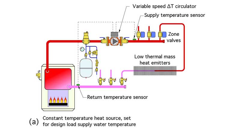
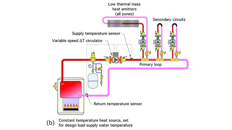
What I found is that imposing a fixed ∆T between supply and return can work when the following conditions are all present:
- Multiple heating zones are controlled with valves, or multiple secondary circulators supplied from a common primary loop;
- The system uses low thermal mass heat emitters; and
- The heat sources maintain a constant supply water temperature, at the design load value, whenever any zone is calling for heat.
Figure 1 shows examples of two systems that meet these criteria.
Consider a low thermal mass hydronic heating system that supplies design load heat output when all zones are active and the supply water temperature remains constant at the design load value. If the heat emitters were not oversized for the design load, all zones would, in theory, remain on until the design load condition subsided (or other factors such as internal gains or intentional thermostat setbacks began influencing the zone loads).
When design load is no longer present in one zone, and the associated thermostat turns off the zone valve or secondary circulator, less heat is being removed from the distribution system. This change reveals itself as an increase in return water temperature (assuming that the supply water temperature remains constant). The temperature difference (e.g., ∆T) between the beginning and end of the distribution system decreases.
A circulator operating based on constrained ∆T would sense this decrease and respond by reducing speed so that the design load ∆T was re-established for the zones that remain active. This process would repeat when another zone turned off. This method of control reduces circulator energy use during partial load conditions.
When a zone turned on, and the supply water temperature remains fixed at the design load value, the return water temperature decreases because more heat is being removed from the distribution system. A circulator operating based on constrained ∆T logic would sense this increase in ∆T and respond by increasing speed to reestablish the design load ∆T.
Mass matters
The requirement that the distribution system have low thermal mass heat emitters implies that the temperature changes on the return side of the system would appear quickly as zones turn on and off. A high thermal mass distribution system, such as a heated concrete floor slab, could significantly delay these temperature changes due to heat being absorbed into or released from the thermal mass. The mounting of the temperature sensors could also affect how quickly the electronics in the circulator respond to the change in temperature.
The constrained ∆T method of control forces the active portion of the system to operate as if it is always at design load conditions. When a zone doesn’t require design load heat input the thermostat for that zone would have to cycle the zone valve or secondary circuit circulator on and off to avoid overheating the space. This, in effect, directs “pulses” of heat into each zone whenever its thermostat calls for heat. The rate of heat delivery during each pulse remains at the design load rate. The duration of each pulse is the time that the zone valve or zone circulator is on. The design load heat transfer rate multiplied by the “on-time” of the zone determines the total heat added to the space during each pulse of heat input. This method of heat delivery has been used in tens of thousands of North American hydronic systems over many decades. It is generally acceptable if the thermostat differential and boiler high limit differential are reasonable.
It’s important to understand that not all hydronic systems meet the three previously stated constraints. Many modern systems use outdoor reset control to vary the water temperature supplied to the distribution system based on outdoor temperature. When outdoor reset control is combined with a circulator operating on constrained ∆T logic, the heat output from the distribution system decreases faster than it should based on outdoor reset control theory. This could lead to a reduction in building comfort under partial load conditions. For this reason, I recommend that circulators using constrained ∆T control only be used in systems that meet all three of the previously stated constraints.
Delta-P control
Differential pressure (e.g., ∆P) speed control is intended for use in hydronic systems that use any type of valve-based zoning (e.g., zone valves, thermostatic radiator valves, or manifold valve actuators).
A ∆P circulator operates by continually comparing its pressure differential against some reference condition. The latter could be a fixed value (e.g., constant ∆P control), or a calculated value based on flow rate (e.g., proportional ∆P control).
Constant ∆P is preferred when most of the head loss of the distribution system occurs in the branch (e.g., zone) piping, rather than the “common piping” through which all system flow passes. This is typical for “homerun” distribution systems.
Proportional ∆P control is preferred when the head loss in the piping mains (rather than the branches) is a large portion of the overall head losses. The latter is typical for “2-pipe” direct-return or reverse-return systems.
A ∆P circulator determines its current ∆P based on the electrical load on the motor, specifically the position of the rotor shaft relative to the magnetic field applied to stator coils. It uses this information along with a “mapping” of motor operating characteristics to infer both its flow rate and ∆P. It then adjusts motor speed up or down to bring its operating condition as close to the target value as possible.
∆P control of modern circulators with ECM motors does not require any external hardware such as pressure transducers or variable frequency drives. Response time is short - a few seconds. This is an advantage over ∆T control that depends on the temperature response of two sensors.
∆P control does require the installer to set the circulator for the required ∆P (or in some cases the required head) of the distribution system at design load conditions. Some installers balk at this requirement, claiming they have no way of determining it. My response to this is: How do you know what size circulator is needed if you haven’t attempted to estimate its operating point when all zones are operating? This is a “hydronics 101” skill. There are manual and software methods for making this estimate. It’s not something that should be guessed at.
Summary
Both ∆T and ∆P methods of circulator speed control can work, given the right application and adherence to the constraints mentioned above. Both have been used in the field for several years. Looking ahead, it’s likely that even more refined methods of circulator speed control will be developed, based on multiple sensed inputs, as well as coordination with other hardware in the system, such as boilers or heat pumps.
Looking for a reprint of this article?
From high-res PDFs to custom plaques, order your copy today!


