Hydronics Workshop
John Siegenthaler: What I look for
A 'dirty dozen' things that point to trouble ahead.
I’ve had lots of opportunities to review plans for pending hydronic heating systems. I’ve also been on “forensic” visits to sites with improperly performing systems. Of the two, I much prefer plan review over forensics. It’s a lot easier to identify and correct issues when they only exist as CAD files or drawings compared to installed hardware in the basement of a disgruntled owner.
Here’s a summary of some of the issues that have shown up on a regular basis.
1. Pumping ‘toward’ the expansion tank
The proper relationship between the location of an expansion tank, and the system circulator(s) has been discussed in many PM columns spanning multiple decades and multiple writers. My colleague Dan Holohan even wrote a book on this subject called “Pumping Away.”
In case you’ve never come across that information, here’s the concept one more time: The expansion tank needs to be connected close to the inlet of the circulator.
When this is done, the differential pressure developed by the circulator adds to the static pressure in the system. This helps drive air from the system rather than allowing air to be inadvertently sucked into the system. It also helps prevent circulator cavitation by elevating the system pressure, and thus maintaining the water farther away from its vapor pressure. It’s one of the first details I look for when reviewing a hydronic piping schematic.
2. Combining a primary loop with headers
Don’t morph the concept of a primary loop with that of a common header type distribution system, as shown in Figure 1.
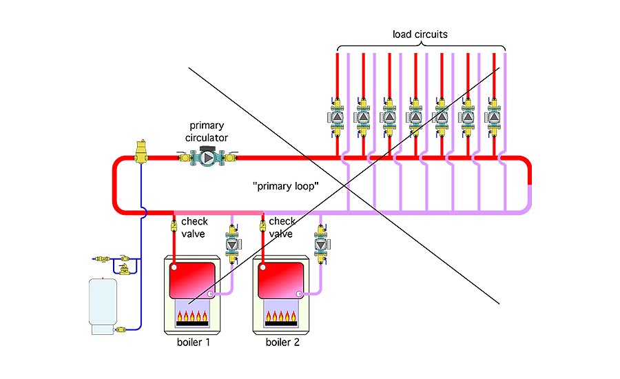
Enlarge Figure 1
Piping a system this way will guarantee heat migration into circuits that are supposed to be off due to the pressure differential developed by the loop circulator. It’s also wasteful of electrical energy. The designer needs to decide — up front — if it will be a true primary/secondary system, or a header system. Either is possible, and either can work fine, just don’t try to blend them together.
3. Swing check valves in vertical piping
Swing check valves rely on gravity to swing their internal “flapper” disk downward against its seat. If installed vertically, the flapper can get “hung up” in the open position. If sufficient reverse flow occurs, the flapper disc can suddenly get pulled back into the flow stream, and instantly slam shut against its seat. The resulting water hammer will surely get the attention of building occupants. The shock wave that’s generated could also fracture dedicated components such as flow meters or pressure gauges.
Always install swing check valves in horizontal piping, bonnet up, and with a minimum of 12 pipe diameters of straight pipe upstream of the valve. The latter helps calm turbulence induced by other components, and thus reduces the chance of metallic “clinking sounds” from the swing check. Spring loaded check valves can be installed in any orientation, but still need a minimum 12 pipe diameters of straight pipe upstream of their inlet.
4. Vertical flow jets in thermal storage tanks
Many hydronic systems, especially those involving renewable energy heat sources, require substantial thermal storage tanks. It’s not enough to just select a tank with the required volume and pressure rating. To preserve stratification within the tank, it’s very important to introduce incoming flows in ways that prevent vertical flow jets within the bulk volume of the tank. Horizontal inlet pipes placed near the top and bottom portions of the tank help. Another option is to use internal diffuser plates near top and bottom tank inlet connections, as shown in Figure 2.
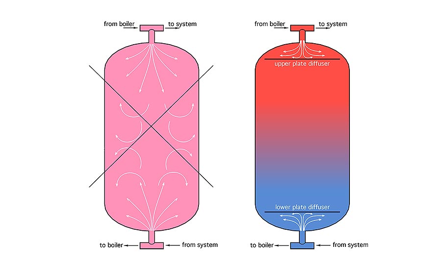
Enlarge Figure 2
5. Improperly located or installed temperature sensors
Controls can only react to what they “feel,” and in heating systems, temperature sensors are their most common “fingertips.” A $15 sensor in the wrong location can bring a $30,000 system to a standstill. Installation drawings should always show the exact location and mounting instructions for all temperature sensors used in the system.
Common sensor installation errors include:
- Mounting one or more sensors in the wrong location;
- Fastening sensors to piping where high surface temperatures are possible using common nylon pull ties that will eventual harden and fracture;
- Not insulating around the sensor, as well as insulation several inches upstream and downstream of the sensor when it’s mounted to a pipe;
- Allowing air to pass between the sensor and surrounding insulation;
- Not using thermal grease with sensors mounted in wells;
- Using a well with a diameter much larger than the sensor diameter;
- Not inserting the sensor to the end of the well;
- Poor connections between sensor leads and wiring back to controller;
- Undersized sensor wiring that adds significant resistance to circuits using thermistor sensors; and
- Routing non-shielded sensor cable within tight enclosures containing line voltage AC wiring.
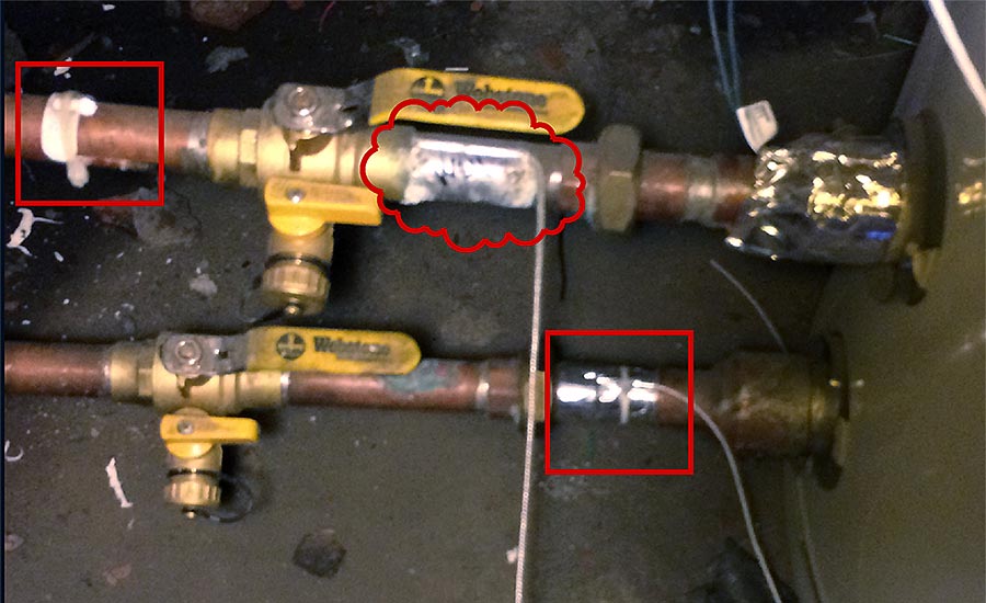
Figure 3 shows several temperature sensors near the bottom of a thermal storage tank.
Enlarge Figure 3
The sensor seen inside the red cloud under the ball valve handle is supposed to report the temperature in the lower portion of the tank. Not only is it not measuring the temperature inside the tank, it’s not insulated from the surrounding air temperature, and it’s fastened to the pipe using aluminum foil tape. As installed, it’s going to report a temperature that’s likely to be significantly different from the temperature in the lower portion of the tank. The two temperature sensors shown in the red squares, which are part of a data acquisition system, are also uninsulated, and thus reporting a temperature somewhere between the pipe surface temperature and the surrounding air temperature.
6. Lack of boiler protection against flue gas condensation
“Any boiler can be a condensing boiler.” That quotation is from Don Pratt, a now-retired trainer from Mestek, and it’s one of my favorites. Given a suitably low inlet water temperature, any boiler burning a hydrocarbon fuel (gas, oil or wood) will operate with sustained flue gas condensation. Boilers that are not designed to operate under such conditions will quickly succumb to corrosion and scaling. So will their vent connector pipes. Masonry chimneys can also be destroyed by the effects of sustained flue gas condensation.
The solution is to provide a proven means of boosting boiler inlet temperature above the likely dewpoint of the exhaust gases within the boiler. This can be done using a 3-way motorized valve, a 3-way thermostatic valve, a 4-way motorized mixing valve or by controlling the speed of a variable-speed circulator that is properly piped as a “thermal clutch” between the load and the boiler. In every case, the means of protecting the boiler must be able to sense boiler inlet temperature and react to it. Any type of mixing hardware that doesn’t have the “smarts” to sense boiler inlet temperature is not going to protect the boiler under all circumstances. A simple boiler bypass pipe — with or without a circulator — but lacking the ability to sense and react to boiler inlet temperature, cannot protect a boiler against sustained flue gas condensation under all conditions.
7. Lack of hydraulic separation between simultaneously operating circulators
Almost every modern hydronic system contains circulators that, at times, operate simultaneously. The ideal scenario is when any circulator that happens to be operating at the same time as another circulator cannot “feel” the presence of that other circulator. That’s called hydraulic separation, and there are several ways to achieve this desirable condition. Several of my past PM columns have discussed the options. Still, systems continue to be constructed that don’t respect the need for hydraulic separation. The results will vary from one system to another, but often manifest themselves as either a lack of adequate heat delivery when and where it’s needed, or too much heat being delivered when and where it’s not needed. If you design hydronic systems, you need to fully understand hydraulic separation and use it in systems where there will be two or more simultaneously operating circulators. Learn it, savor it and apply it.
8. Flow bottlenecks
One of the most common “generic” issues with underperforming hydronic systems is what I call a “flow bottleneck.” Some component in the flow path is inadvertently creating high flow resistance, and severely limiting the flow rate, and thus the heat delivery rate of the circuit.
A common example is a 3-way thermostatic mixing valve with a Cv of perhaps 2.5 to 3 installed as a mixer to a radiant panel manifold station with several circuits that requires a total flow rate of 8-12 gpm. A mixing valve that creates 1-psi pressure drop with a flow of 2.5 gpm (e.g., a valve with a Cv of 2.5) would create over 10 psi pressure drop if there was 8 gpm passing through it. Considering the the circulators often used on such a manifold can only produce about 4-5 psi differential at zero flow, the actual flow rate to the manifold is going to be a fraction of what’s anticipated, and the heat delivery is going to suffer big time.
The take away: Don’t size mixing valves based on pipe size. Size them based on Cv. A valve with a Cv that’s about equal to the flow rate required in the manifold at design load is usually appropriate.
Don’t size mixing valves based on pipe size. Size them based on Cv. A valve with a Cv that’s about equal to the flow rate required in the manifold at design load is usually appropriate.
9. Heat transfer bottlenecks
The other “bottlenecks” that can occur are based on heat transfer. If device A puts out 50,000 Btu/h, and device B can only absorb 25,000 Btu/h while operating at some nominal expected water temperature, there’s going to be a problem. Simply put, device A will “gain” on device B until some safety device turns off device A. The “on” time might only be a minute or two. Then, the cycle is likely to repeat itself. An example is a heat pump trying to push heat at a rate of say 48,000 Btu/h through a heat exchanger, that, at an incoming water temperature of 120° F on the hot side, and 110° on the “cooler” side, can only transfer 20,000 Btu/h. The water temperature going through the heat pump’s condenser quickly climbs, and the compressor turns off on either a high refrigerant pressure switch or some internal temperature protection controller. Given a small amount of fluid between the heat pump and the heat exchanger, the cycle quickly repeats. The result will be thousands of short cycles over the course of a typical heating season, which will likely cause premature component failure within the heat pump.
Always generously size your heat exchangers. If you don’t have documentation that defines the heat exchanger’s performance at the conditions at which you intend to operate it, contact the manufacturer and get their recommendation. It’s better to hear “our product can’t meet you performance requirement” upfront, before thousands of dollars worth of hardware gets installed, only to be crippled by a heat transfer bottleneck.
10. Lack of purging provisions
Every branch circuit in a hydronic system should have a means of expediently getting air out and water in. A float-type air vent at the high point of the circuit might help, but it’s no substitute for the air entrainment capability of forced water purging. There are many combination purging valves currently available for residential and light commercial systems. In larger systems, the functional equivalent of a combination purging valve can be produced using an inline full-port ball valve in combination with an upstream tee and another ball valve that can handle to purging flow rate. As a guideline, purging flow velocities through piping should be at least 2 feet per second. Even higher flow velocities are preferred for fast purging.
11. Turbulence inducing component near circulator inlet
Any component that creates turbulence near the inlet of a circulator can increase the noise level of that circulator or even cause cavitation within the circulator. Common offenders include circulators that are mounted just above a tee in a header or just downstream of an elbow, clogged basket strainers, or balancing valves installed just upstream of circulators. As a rule, install at least 12 pipe diameters of straight pipe upstream of any circulator inlet. Show this on your schematics, and write it into your specifications.
12. Lack of counterflow within heat exchangers
All heat exchangers work best when the two fluids exchange heat flow in opposite directions. This is called “counterflow,” and it’s one of the first things to check out when looking over a schematic for a hydronic system involving a heat exchanger. Counterflow increases something called the “log mean temperature difference” across the heat exchanger. Think of this as the “effective ∆T” that drives heat from the hot side to the cooler side. The higher the effective ∆T, the higher the rate of heat transfer, all other conditions being the same.
The “dirty dozen” issues described above are not an exhaustive list of possible problems in hydronic systems. Still, they go a long way in scrutinizing designs and identifying potential problems before they become expensive callbacks. Use them as you review your own designs and those from other sources.
Evgen_Prozhyrko/iStock / Getty Images Plus via Getty Images. Figures courtesy of John Siegenthaler.
Looking for a reprint of this article?
From high-res PDFs to custom plaques, order your copy today!


