John Siegenthaler: Chump change
The minuscule cost of operating a well-designed hydronic distribution system.

Hydronic heating professionals often promote the concept that current generation mod/con boilers can operate with AFUEs in the range of 95% and above. Professionals who install geothermal water-to-water heat pumps often boast their equipment is capable of coefficients of performance (COPs) in the range of 3.0 to perhaps 3.5. These performance numbers are possible given the right equipment, the right application and a specific definition for thermal efficiency and COP used when evaluating the equipment.
However, most of these same hydronic pros don’t bother to describe how a well-designed and properly installed hydronic heating system has a distribution efficiency much higher than that of either a forced air system or a system that moves heat through a building using refrigerant.
Beyond thermal performance acronyms
For a heating system to be considered best-in-class, it needs a high efficiency heat source and the ability to move heat through a building using minimal amounts of electrical energy. The latter criteria can be quantified using the concept of distribution efficiency, as defined by Formula 1.
Formula 1:
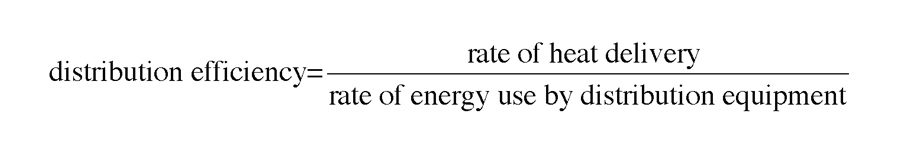
Distribution efficiency has nothing to do with converting electricity or any type of fuel into heat. Instead, it describes how many Btu/h of heat the distribution system can move from the heat source to the heat emitters for each watt of electrical power supplied to operate that distribution system. The more heat the distribution system can deliver per watt of electrical power input, the higher its distribution efficiency.
To show how wide the gap is between two contemporary systems, I’ll compare a relatively simply hydronic heating distribution system using currently available off-the-shelf hardware to a forced air system on a state-of-the-art geothermal heat pump.
The hydronic system assumes a building with a design heating load of 30,000 Btu/h. The building will be heated using eight identical panel radiators measuring 24 inches high by 72 inches long by 4 inches thick. Figure 1 shows an example of one such radiator.
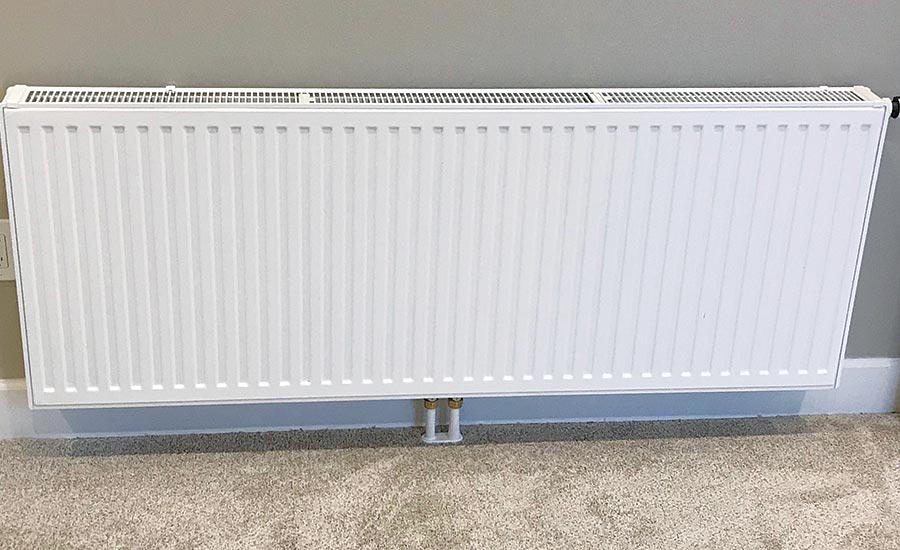
These relatively large panels were selected so the building’s design heating load could be met using a supply water temperature to the radiators of 120° F, along with a 20° temperature drop. That temperature makes the system very well suited for mod/con boilers, geothermal water-to-water heat pumps and air-to-water heat pumps. Those eight radiators, operating under these conditions, put out a total of 30,800 Btu/h, just a bit more than the design load.
The piping for this system is very simple, and is shown in Figure 2.
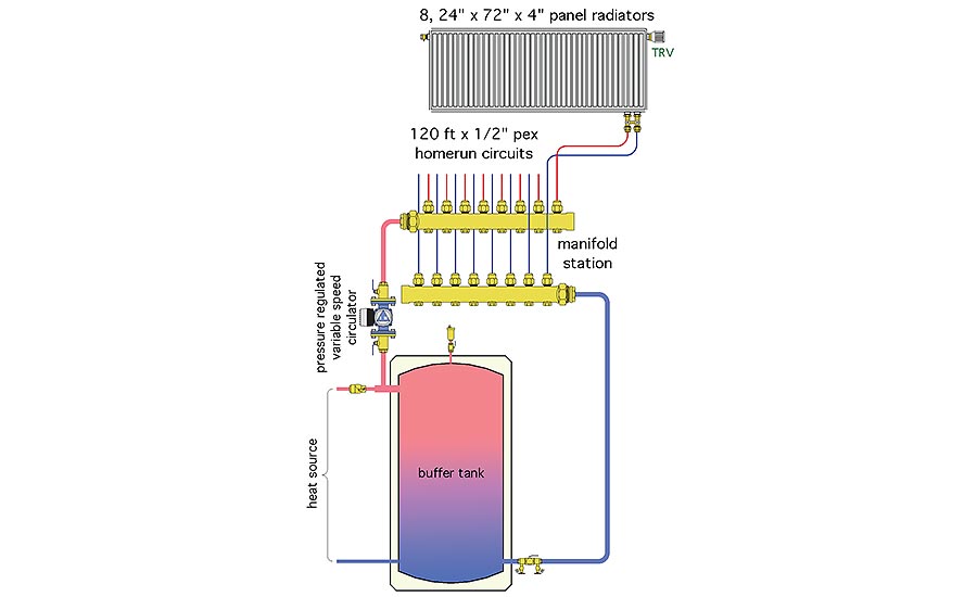
The system uses wireless thermostatic radiator valves, which allow each radiator to function as an independent zone. Each room can individually respond to internal heat gains, temperature setbacks and personal comfort preferences.
Each radiator is connected to a manifold station by 120 feet of 1/2-inch PEX tubing (60 feet on supply, plus 60 feet on return). The result is a simple homerun distribution system.
A buffer tank is shown between the heat source and distribution system. Its purpose is to prevent heat source short cycling given the relatively low design load combined with a highly zoned distribution system.
From the standpoint of distribution efficiency, the heat source warming the buffer tank is irrelevant. It’s the hydraulics of the distribution system and those of the variable speed pressure-regulated circulator that matter.
The total system flow rate required to deliver 30,800 Btu/h with a 20° temperature drop is only 3.1 gpm. This divides up equally among the panels so each circuit only requires 0.39 gpm.
The combined head load of the 120 feet of PEX tubing and the panel radiator at this small flow rate is only about 4.2 feet of head. Let’s add another 10% to this head loss to account for some head loss in the short 1-inch piping connecting the manifold station to the buffer tank.
The circulator duty point in this system is therefore 3 gpm at 4.6 feet of head.
Paltry power
The flow rate and head requirement can be used to estimate the electrical power input to a circulator. To be conservative, I assumed a modern ECM circulator with a wire-to-water efficiency of 30% at the calculated duty point.
The estimated electrical input to the circulator can be calculated using Formula 2.
Formula 2:
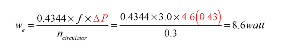
Where:
We = estimated electrical input wattage to circulator (watts);
f = flow rate (gpm);
∆P = pressure differential across the circulator (psi);
ncirculator = wire-to-water efficiency of circulator (decimal percent); and
0.4334 = unit conversion factor
The multiplication of 4.6(0.43) represent the head requirement converted to differential pressure (e.g., ∆P), which is necessary to make Formula 2 valid.
If a circulator operated continuously for 24 hours at this power input, and at a location where electricity costs $0.20 per kWh, the total daily operating cost would be a measly 4.1 cents! If the circulator operated continuously throughout a heat season lasting 3,500 hours at the same input wattage, the total cost would be about $6. I suspect that most homeowners could work that into their budget.
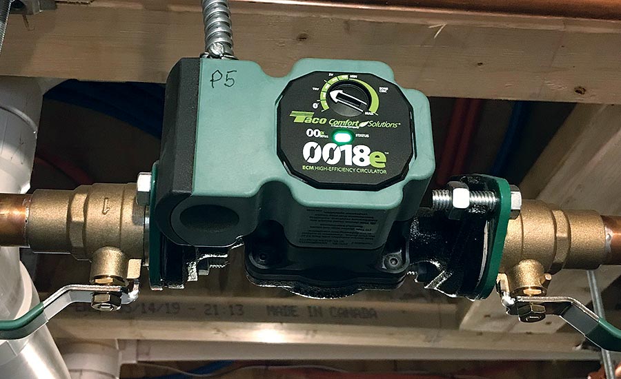
A few years ago, you would not have been able to find a circulator that could operate at such low power. Today, there are several circulators on the North American market that can operate in the sub-10 watt power range. One example is shown in Figure 3.
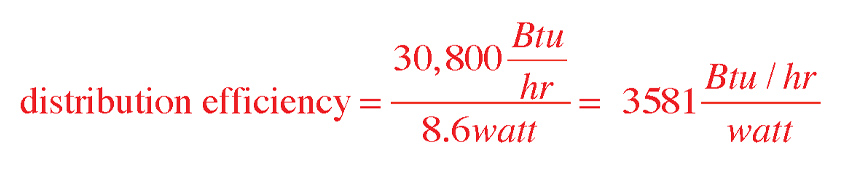
The distribution efficiency of the example hydronic distribution system can be calculated using Formula 1:
An interesting comparison
So how does a distribution efficiency of 3,581 Btu/h/watt rank relative to that of other systems?
To put this number in perspective, let’s compare it to the distribution efficiency of a modern geothermal water-to-air heat pump with a variable speed ECM blower motor.
One manufacturer lists the wattage of an ECM blower on a nominal 4-ton (48,000 Btu/h) rated water-to-air heat pump at full speed as 746 watts. Assuming that the heat pump delivers 48,000 Btu/h using 746 watts input to the blower, its distribution efficiency would be:
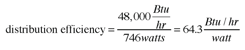
The two calculated distribution efficiencies can be compared by making the numbers into a ratio: 3581/64.3 = 55.7. This means the hydronic system is delivering almost 56 times as much heat to the distribution system, per watt of electrical input energy, compared to the heat pump using forced air distribution.
The inverse of that ratio, 64.3/3581 = 0.018, or 1.8%, implies that the hydronic system delivers heat to the building using only about 1.8% of the electrical input power required by the forced air system.
Either way you look at it, the hydronic system in this comparison is far more efficient when it comes to delivering heat.
This is not meant as a put down on the geothermal heat pump used in the comparison. That heat pump’s thermal efficiency could be excellent (perhaps a COP of 4.0 or more). However, because the heat pump uses air rather than water to deliver heat, its distribution efficiency is very low in comparison to the hydronic system.
Go tell it
The concept of high distribution efficiency should be a starting point — rather than an afterthought — when discussing the advantages of a modern hydronic systems. Our industry needs to get this message to trade allies, such as architects and engineers involved with low energy or net-zero buildings, energy auditors, professionals involved in thermally-based renewable energy heat sources and regulators who determine which HVAC technologies are incentivized through government programs.
The superior distribution efficiency of hydronic systems could — and should — play an important role in shaping what are likely to be inevitable carbon reduction goals. That’s not going to happen if our industry isn’t proactive. There are lots of technically competent decision makers who have never heard about distribution efficiency. I suspect many of them would embrace the concept based on real comparisons. It’s time we tell them what’s possible.
Looking for a reprint of this article?
From high-res PDFs to custom plaques, order your copy today!


