John Siegenthaler: Bidirectional Btu
The flexibility of hydronic systems.
Over the years, our office has received requests for design assistance for systems involving two hydronic heat sources, each in different buildings, where the expectation is to have either heat source supply heat to either building. One situation involved a mod/con boiler in a house along with a cordwood gasification boiler with thermal storage tank in a heated outbuilding located about 100 feet from the house. Both buildings had zoned slab type floor heating.
The owner wanted to use heat from the cordwood gasification boiler, when available, to heat the outbuilding and the house. The mod/con boiler would serve as the auxiliary heat source for both the house and the out building during times when the cordwood boiler was either off or unable to meet the load.
Although this sounds like a reasonable request, it’s definitely not a routine installation. Heat would need to flow in both directions through insulated underground piping between the two buildings. Other considerations included the fact that water heated by a cordwood boiler is often much hotter than required by floor heating circuits. The water temperature from the cordwood boiler would also vary over a wide range, depending on its firing status.
The layout
The piping concept I suggested for this system is shown in Figure 1.
> FIGURE 1.
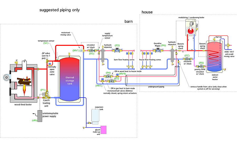
Let’s examine this system starting on the house side.
When the mod/con boiler needs to supply heat to house zones, it operates based on outdoor reset control. Circulator (P7) provides flow between the mod/con boiler and a hydraulic separator. The latter isolates the pressure dynamics of circulator (P7) from those of the variable-speed pressure-regulated distribution circulator (P6). It also provides air, dirt and magnetic particle separation in this portion of the system. The speed of circulator (P6) changes to maintain a set differential pressure across the distribution headers as the zone valves in the house open and close.
Domestic hot water is provided by an indirect water heater that’s operated as the priority load for the mod/con boiler. When domestic water heating is active, circulator (P8) is on, circulator (P7) is off and the mod/con boiler targets a higher supply water temperature.
Cordwood considerations
The cordwood gasification boiler and its associated thermal storage tank, can be thought of as the “biomass heat source.” Heat can come directly from the boiler if it’s operating or from the thermal storage tank if the boiler is off or possibly from both, depending on the flow rate of hot water required by the load relative to that through the boiler.
Cordwood gasification boilers produce their highest efficiency and lowest emissions when “batch fired.” Once a small fire is kindled and some coals have formed, the upper combustion chamber is completely filled with cordwood and the boiler’s blower is turned on. The objective is to incinerate the chamber full of wood as quickly as possible, and dump the resulting heat to the load or into thermal storage.
The high rate of combustion can produce secondary combustion chamber temperatures in excess of 2,000° F, which minimize emissions and produce average burn cycle efficiencies in the range of 70% to 75%.
The loading unit between the cordwood boiler and thermal storage tank contains a high flow capacity thermostatic mixing valve and a circulator. Its purpose is to keep the inlet temperature to the cordwood gasification boiler above 130° whenever possible. This prevents sustained flue gas condensation, which could otherwise cause severe corrosion of the steel boiler and its venting system. When necessary, the loading unit mixes some of the hottest available water leaving the boiler with cooler water returning from the load or the lower portion of the thermal storage tank.
The ∆P valve seen between the cordwood gasification boiler and thermal storage tank is set for a forward opening pressure of 1 to 1.5 psi. That’s sufficient to prevent cool water returning from the load from migrating through the boiler when it’s off. It’s also low enough that the ∆P valve opens immediately when the loading unit circulator starts. The ∆P valve also prevents forward or reverse thermosiphoning between the thermal storage tank and boiler when the loading unit circulator is off.
The normally open zone valve seen just below the ∆P valve opens during any power outage. Its function is to allow a bypass of the ∆P valve so that forward thermosiphoning between the boiler and thermal storage tank is possible during a power outage. This allows residual heat from the boiler to be absorbed by the thermal storage tank.
The schematic also shows an (optional) uninterruptible power supply (UPS) that could be installed to keep the circulator in the loading unit operating for a nominal 30 minutes into a power outage. This is not an essential component given the other details for moving residual heat from the boiler during a power outage, but it’s a relatively simple and inexpensive add-on that I recommend in situations where power outages are common.
Circulator (P2) draws hot water from the biomass boiler or thermal storage tank through a motorized 3-way mixing valve (MV1). The controller associated with this valve operates based on outdoor reset. This reduces the temperature of what could be very hot water coming from the biomass heat source to a value suitable for the floor heating circuits. Keeping the mixing valve on the cordwood boiler side of the system also allows the underground piping to the house to operate at the lower temperatures, which reduces heat loss to the ground. This is a subtle but very desirable detail.
The hydraulic separator to the right of circulator (P2) provides the same functions as the hydraulic separator in the house. These include isolating the pressure dynamics of circulators (P2) from those of (P3), as well as the pressure dynamics of (P4) or (P5) from those of (P2) and (P3). This separator also provides air, dirt and magnetic particle separation for the out building portion of the system.
The out building is also heated by floor circuits supplied through zone valves. Flow is created by a variable-speed pressure-regulated circulator (P3).
Changing direction
The need to move heat produced by the mod/con boiler from the house to the out building, as well as heat produced by the cordwood gasification boiler from the out building to the house, requires flow reversal through the underground piping. There are multiple ways to do this. They include:
- The combination of a single circulator with 4-way/2-position reversing valve.
- Two circulators pumping in opposite directions, where the active circulator pushes flow backward through the inactive circulator.
- Two circulators pumping in opposite directions, in combination with a motorized 3-way diverter valve.
- Two circulator pumping in opposite directions, each equipped with a motorized ball valve that closes when its associated circulator is off.
There are advantages and limitation with each of these approaches. One limitation that’s common to methods 1, 2 and 3 is that there is always an unblocked flow path through the underground piping between the house and out building. If the out building is being heated from the biomass heat source or the house is being heated by the mod/con boiler, there will be a slight pressure drop established across one of the hydraulic separators by circulator (P2) or (P7). This small but undesirable differential pressure is illustrated in Figure 2, which assumes use of a 3-way diverter valve to determine flow direction.
> FIGURE 2.
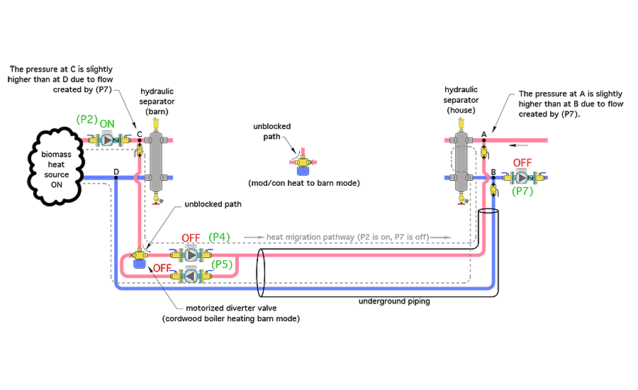
A small differential pressure will develop between points A and B (house side of system when circulator P7 is on), or between points C and D (out building side of system when circulator P2 is on). Those differential pressures will establish a slow but persistent flow of heated water through the underground piping because there is no component that completely blocks that flow path. Such a flow needlessly increases heat loss from the underground piping.
In method 4, the two motorized ball valves, each equipped with a normally closed spring-return actuator, completely block heated water from migrating through the underground piping circuit, when circulators (P4) and (P5) are both off, and circulator (P2) or (P7) are operating. The motorized valves should have full-port bodies with high Cv ratings to minimize head loss. Each would be wired to open when its associated circulator (P4) or (P5) is turned on. Each valve would be closed by a spring return actuator as soon as its associated circulator turns off.
Ideally, points A and B should be located as close to the house hydraulic separator as possible. Likewise, points C and D should be located as close to the out building hydraulic separator as possible. Doing so minimizes the differential pressure developed across the separators.
Pressure equalization of the out building and house portions of the system takes place through the underground pipe (shown in blue). This portion of the piping does not contain circulators or motorized valves. This path must remain unblocked to ensure pressure equalization.
A single expansion tank sized for the entire system volume, or multiple smaller tanks piped in parallel, should all connect to the system at one location. This avoids creating multiple points of no pressure change in the system by having expansion tanks at multiple locations. Figure 1 shows the expansion tank connected to a lower port on the thermal storage tank associated with the cordwood gasification boiler.
Control concept
The primary objective of this system is to use heat supplied by the biomass heat source whenever possible, and only supplement that heat using the propane-fired mod/con boiler when necessary. Thus, the key control parameter is the temperature of water available from the biomass heat source. A call from any zone thermostat in either building zone initiates a controller that looks at the temperature of the upper storage tank header sensor (S1).
If temperature of (S1) is greater than or equal to some minimum value that can provide acceptable comfort in either building, the biomass heat source provides the necessary heat. Circulator (P2) and mixing valve (MV1) operate. If a zone in the out building is calling for heat, circulator (P3) is turned on. If a zone in the house is calling for heat, circulator (P6) (P4) and motorized ball valve (MV4) are turned on.
When setting the minimum temperature criteria for using the biomass heat source, keep in mind that there will be some temperature drop through the underground piping. Thus, the water temperature arriving at the house hydraulic separator from the out building will be slightly lower than that arriving at the out building hydraulic separator.
If temperature at (S1) is less than the minimum value for floor heating, the mod/con boiler is fired along with circulator (P7). If the zone calling for heat is in the house, turn on circulator (P6). If the zone calling for heat is in the out building, turn on circulators (P3), (P5) and motorized ball valve (MV5).
The controller making the decision for the minimum temperature at sensor (S1) should have a suitable differential to prevent abrupt changes in which heat source is called when a load occurs.
Versatility
Although this system is a bit out of the ordinary, it demonstrates how readily available hydronics hardware can be crafted to the needs of very specific situations. It also embodies best practices such as hydraulic separation, variable speed pumping and reducing extraneous heat loss. Perhaps you can use it, or some variant of it, in a future application.
To read Siegenthaler’s article: “Bidirectional Btu” in pdf form, please see here.
Looking for a reprint of this article?
From high-res PDFs to custom plaques, order your copy today!


