John Siegenthaler: A synergistic system
True professionals look for synergistic opportunities when designing hydronic systems.
One of the “delights” of designing hydronic systems is looking for synergistic opportunities, where one device provides multiple functions or benefits that would otherwise require two or more separate devices. For example, it’s possible for a buffer tank to provide hydraulic separation of the circulators in a system while it also adds stabilizing thermal mass. The latter was the intended function of the tank, the former was a synergistic benefit that eliminates the need for other hardware to provide a necessary function (e.g., hydraulic separation). Such opportunities usually reduce installed cost, complexity and time.
> FIGURE 1.
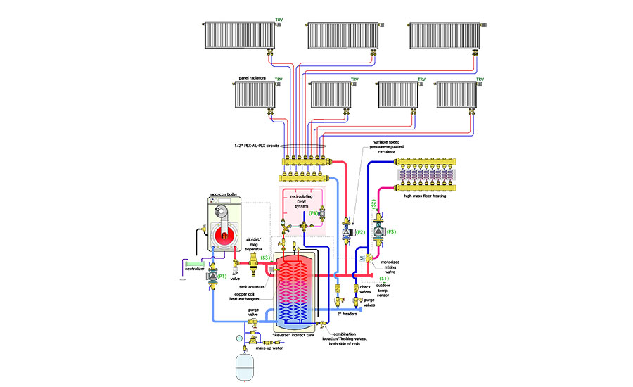
Figure 1 shows a system that has several synergistic elements.
This system was developed to provide space heating and domestic hot water for a new home. The heat source is a mod/con boiler with a nominal 100,000 Btu/h output. The home’s first floor is slab-on-grade with ceramic tile flooring. It’s perfectly suited to floor heating. The second floor has several rooms, some of which are only occasionally used. This situation is well suited to panel radiators, each equipped with a thermostatic valve. Each radiator can function as an independently-controlled zone, provided that heated water is available, and that a circulator is operating to push flow through any radiator with an open valve.
Don't get short-cycled
Highly zoned hydronic distribution systems set the stage for heat source short-cycling. In this system, the fact that the mod/con boiler can modulate down to about 20% of its rated heating output helps reduce this possibility, but doesn’t eliminate it.
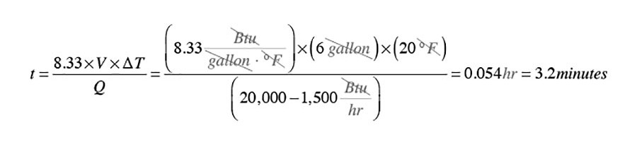
For example, the boiler in this system has a minimum heating capacity of about 20,000 Btu/h. If only one panel radiator is calling for heat, the load could be as low as 1,500 Btu/h. If we assumed that the combined thermal mass of the water in this zone circuit, along with the metal in the boiler’s heat exchanger and the panel radiator, is equivalent to 6 gallons of water, and that the operating differential of the boiler is 20° F between burner on and burner off, the boiler’s on-cycle under minimum heat output would only be about 3.2 minutes. Here’s the associated math.
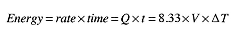
Where:
Q = Net rate of heat transfer to the zone (Btu/h)
t = boiler on time (hour)
8.33 = Btu absorbed per gallon of water per °F
(Btu/gal/°F)
V = volume of water in zone (gallon)
∆T = temperature rise of water in the zone (°F)
Rearranging the terms to solve for boiler on time (t), and plugging in the numbers yields:
The classic solution to prevent short cycling is to install a buffer tank. Given all those independently-controlled panel radiators, this system definitely needs such a tank. It also needs to provide domestic hot water using the boiler as the heat source. The classic solution: Include an indirect water heater. Two separate tanks for two separate functions.
If there’s sufficient space to install both tanks, and the project budget supports the installed cost of both tanks, I can’t argue that this “two tank” approach won’t work. However, I can advise that it’s possible to buffer the space heating loads and supply domestic hot water from a single “reverse” indirect tank, as shown in Figure 1.
A reverse indirect has a carbon steel pressure vessel that holds “system water,” (e.g., the same water that passes through the boiler and balance of system). Domestic cold water enters the multiple copper tube heat exchange coils at the lower right side of the tank, and rises upward. If the water in the tank shell is maintained at a sufficient temperature, the entering cold water can be fully heated to or above the desired domestic hot water delivery temperature as it rises through the coils. This “on-demand” water heating occurs whenever domestic hot water is drawn from a fixture.
The mod/con boiler fires whenever the tank temperature, as measured by the tank’s aquastat, is 120° or less. It remains on until the tank temperature rises to 140°. This temperature cycling range ensures adequate DHW delivery to meet a specific load requirement, in this case a sustained DHW flow of 4 gpm. It also ensures that hot water is available to either space heating subsystem 24/7.
This system includes a domestic hot water recirculating loop, and an ASSE 1017 rated anti-scald thermostatic mixing valve. The latter ensures that hot water entering the recirculation loop doesn’t exceed 120°. The recirculation loop is powered by a small stainless steel circulator. Water on the return side of the loop passes back into the lower end of the internal copper coils, along with cold water to replace the hot water drawn from the fixtures. A lead-free check valve prevents cold water from passing in reverse through the recirculation loop.
The reverse indirect tank is piped in a “two-pipe” configuration. The headers supplying space heating loads tee into the upper and lower tank connections just outside the tank, and pass behind the tank in Figure 1. Keeping these tees close to the tank, and using 2-inch header piping results in very low pressure drop in the piping that’s “common” to circulators (P1), (P2), and (P3), allowing them to be hydraulically separated. This tank piping configuration also allows the possibility of hot water flow from the boiler directly to the space heating loads if they are operating simultaneously.
Simple and efficient
The panel radiators are connected as “home run” circuits, beginning and ending at a common manifold station. This arrangement supplies water at the same temperature to each radiator, regardless of which radiators are operating. It also allows the flow rate to each radiator to be adjusted using a balancing valve built into the manifold station, or within the thermostatic radiator valves.
A variable speed pressure-regulated circulator (P2) automatically adjusts its speed to maintain a constant differential pressure, and thus help keep flow rates through each radiator relatively stable, regardless of which radiators are active. Circulator (P2) can be enabled by a simple switch closure at the beginning of the heat season. If no radiator valves are open, this circulator drops into a “sleep” mode, where it draws less than 10 watts. This circulator could also be enabled based on a set outdoor temperature — such as 55° or less. It could also be turned on and off by a master thermostat in the second floor space. In this case the thermostatic valves on each radiator act as temperature limiting devices.
The high mass floor heating circuits are supplied through a 3-way motorized mixing valve that is regulated based on outdoor reset control.
No “thermal bullying” allowed
The panel radiators have very low thermal mass and require an average water temperature of 120° at design conditions. The heated floor slab has very high thermal mass and requires an average water temperature of 105° at design conditions. Given these characteristics, there’s a possibility that, during a “cool” slab recovery condition, the slab’s thermal mass can absorb heat from the buffer/DHW tank much faster than the boiler can replace it. This would quickly lower tank temperature and temporarily deprive occupants of acceptable DHW delivery temperatures.
To prevent this possibility, a temperature sensor (S3) is installed on the upper tank header as close to the tank as possible and wrapped with insulation. This sensor connects to the boiler protection sensor terminals on the controller operating the 3-way motorized mixing valve. This is where things may seem confusing.
In this system, there is no need to protect the mod/con boiler from operating with sustained flue gas condensation. Quite the opposite, flue gas condensation is beneficial, and the relatively low water temperatures this system operates at encourage such condensation. However, the control action needed to protect a conventional boiler from sustained flue gas condensation can be used to prevent the cool slab recovery condition from rapidly sucking heat out of the buffer/DHW tank. That boiler protection control action is built into most modern mixing valve controllers. It only allows hot water into the mixing valve when the temperature at sensor (S3) rises above a user-selected setpoint, which is 120° in this system. This control action gives priority to maintaining a minimum tank temperature that’s always able to provide acceptable DHW delivery temperature.
By temporarily decoupling the thermal mass of the slab from the remainder of the system, it also allows the panel radiators to provide adequate heating while the slab is recovering. This condition is not expected to occur often, but this simple “synergistic” use of a control function that’s already in the controller’s firmware guards against a complaint such as: “Why is the shower water always cool after I turn up the downstairs thermostat?”
Other synergistic characteristics of this system include:
-
Using remnant lengths of 1/2-inch PEX-AL-PEX tubing, left over from the floor heating circuits, for some of the homerun circuits to the panel radiators;
-
The ∆P valve between the boiler and tank is set for 1 psi opening pressure, this prevents water returning from the space heating loads from migrating through the boiler when it’s off. It also eliminates the need for a check valve to prevent reverse thermosiphon flow from the tank through the boiler circuit;
-
The combination air/dirt/magnetic particle separator provides vital functions, conserves installation space, and reduces installation time, relative to using separate components;
-
The isolation flange on boiler circulator (P1), and the half union on the ∆P valve allow the boiler to be isolated from the balance of system and removed, if necessary. They eliminate the need for unions at the two boiler connections; and
-
The combination isolation/flushing valves on the domestic water inlet and outlet for the tank allow the internal coils to be isolated. They also allow these coils to be flushed with a mild acid solution, if necessary, to remove scale deposits.
Looking for synergistic opportunities when designing hydronic systems is challenging and rewarding. It’s what distinguishes true hydronic professionals from those who simply repeat the same designs, project after project, year after year, without looking for unique circumstances or products that make incremental improvements. Be a pro and keep looking for those opportunities.
To read Siegenthaler’s article: “A synergistic system” in pdf form, please see here.
Looking for a reprint of this article?
From high-res PDFs to custom plaques, order your copy today!


