John Siegenthaler: Tell me more about 'nubbed' foam panels
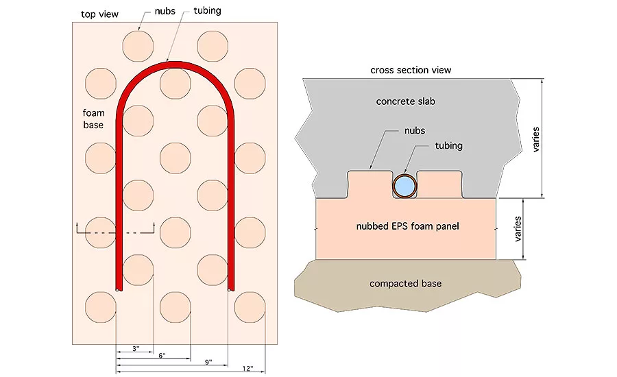
Figure 1. No pull ties, bag ties or plastic staples are needed to hold the tubing in place — it’s held there by friction and the slightly concave surfaces of the staggered nubs. Images provided by: John Siegenthaler
There are several North American manufacturers currently offering expanded polystyrene (EPS) panels that hold PEX, PEX-AL-PEX or PERT tubing between staggered rows of foam “nubs.” These panels are available in various thicknesses and compressive strengths to accommodate slabs in a wide range of buildings. The figure below shows a generic representation of how these panels hold tubing in heated slabs.
The concept is simple: Lay out the nominal 2-by-4-foot panels on a flat and stable base. The edges of the panels lock together to quickly form a tidy grid. Next, uncoil the PEX tubing and “walk” it into place (e.g., press it down with your shoe) between the nubs. The nubs usually allow spacing that is a multiple of 3 inches (6 inches, 9 inches, 12 inches, etc.).
No pull ties, bag ties or plastic staples are needed to hold the tubing in place — it’s held there by friction and the slightly concave surfaces of the staggered nubs. Once the tubing is placed and pressure tested, a layer of welded wire reinforcing is laid over the top, and a concrete slab that’s at least 3 inches thick is poured over the assembly.
This is all clever, convenient and versatile. But what’s missing is thermal performance data for heated slabs installed over these panels.
None of the manufacturers that I researched publish information on the heat output versus average water temperature from slabs poured over their insulating panels. Without such information, how are designers supposed to evaluate the performance of different tube sizes, tube spacing, slab thicknesses and finish floor materials? See Figure 1 above.
Perhaps these manufacturers view that information as someone else’s responsibility. After all, competing manufacturers of flat foam panels don’t publish this type of information.
But there’s a difference. Unlike flat foam products that have many potential uses in construction (such as insulated wall sheathing, roofing insulation, basement wall insulation, etc.), nubbed foam panels are specifically made for holding tubing in predetermined positions and spacing within heated slabs. That’s their sole application.
Designers considering nubbed panel products need information on how these slabs will perform. Otherwise, they’re left to make guesses based on information that doesn’t include the specific nuances of these panels.
Assumption vs. assurance
One might assume that the thermal performance of a heated slab having specified thickness, tube size and tube spacing, and poured over nubbed panels, should be about the same as that of a slab with the same thickness, tubing size and tube spacing poured over flat insulation panels having the same R-value. It’s an understandable assumption, and currently about the only possible comparison, but is it accurate?
I think there are enough differences in the “thermal geometry” between these two approaches to cast doubt on such an assumption.
For starters, with nubbed panel systems, the tubing is held at the bottom of the slab rather than approximately halfway up through the thickness of the slab.
I researched the effect of tubing depth in slabs on thermal performance several years ago and wrote about it in PM in the May 2000 issue (“Depth Perception”).
I used a computer simulation technique called finite element analysis to estimate the surface temperature and upward heat output of concrete slabs where the only variable was tubing depth. I found that tubing at the bottom of a 4-inch slab versus at the mid-height of the slab requires higher water temperature to generate the same upward heat output.
At an upward heat output of 15 Btu/h per square foot, tubing at the bottom of the slab needs water that’s about 7° F warmer than required if the tubing were at the mid-thickness of the slab. That 7° was of little concern in the days when conventional boilers, operating well above the dew point of their flue gases, supplied heat to floor slabs through mixing devices. Just turn up the temperature of the mixing device, leave the boiler alone and call it a day.
However, increasing the water temperature by a few degrees can have a significant impact on the performance of contemporary hydronic heat sources such as mod/con boilers, heat pumps (geothermal water-to-water, and air-to-water) and solar thermal collectors. It also limits the temperature cycling range of thermal storage tanks heated by biomass boilers.
In short, higher supply water temperature is not desirable and shouldn’t be dismissed as inconsequential.
Foam vs. concrete
Just about everyone reading this knows that the R-value of expanded polystyrene (EPS) foam is much higher than that of concrete. The R-value of 1.5 lb/ft3 density EPS is about 5.0 (°F•hr•ft2/Btu) per inch of thickness. The R-value of standard structural concrete is about 0.1 (°F•hr•ft2/Btu) per inch of thickness. That’s a 50:1 ratio in the ability to move heat by conduction.
So what? Isn’t insulation supposed to have a much higher R-value than concrete?
Of course it is, especially when it comes to limiting downward heat loss from the slab.
But think about the hundreds of small surface areas where the tubing contacts the side of each foam nub. In a standard slab, the tubing would be dissipating heat through concrete rather than through foam over these area. The foam is not going to move heat away from the tubing as fast as concrete.
Furthermore, the cross-sectional area of the nubs increases relative to that of concrete as heat moves laterally away from the tubing. The fin efficiency of the combined materials decreases based on more foam and less concrete.
As a comparison, imagine a fin-tube baseboard element where the fins where mostly aluminum where they contact the tubing, but become a mixture of aluminum and foam farther away from the tubing. The farther away from the fin, the greater the proportion of foam. How would you expect that fin-tube element to perform relative to one with fins that are 100% aluminum?
Beyond the contact area between the tubing and nubs is the volume of the foam nubs above the base insulation thickness, and in areas between the rows of tubing. In a standard slab, the total volume of these foam nubs would be concrete rather than EPS. That’s also going to slow lateral heat diffusion away from the tubing.
Figure it out
One way to assess the differences would be to construct two otherwise identical test slabs, one with the nubbed foam panels and the other with flat underside insulation of the same R-value. Use identical tube sizes and spacings in both panels. Then, run some accurate heat transfer tests under identical surrounding conditions.
If the flow rate were held constant, and the inlet and outlet temperatures of the water through the test slabs were accurately measured, the multiplication of flow rate times the temperature drop through the test slab would be proportional to the heat output.
Another approach would require three-dimensional finite element analysis of a small portion of the assembly. Software that can do this is available, and there are consulting companies that specialize in its use. That software is now routinely used in many other industries to study heat transfer in three-dimensional assemblies. Why shouldn’t it be used for creating design tools for accurately predicting the performance of heated floors over specialty insulation products?
I’ll close with a position and a plea.
My position is that I’m not against using nubbed foam panels in floor heating systems. Quite the contrary — I see them as convenient and versatile. They are legitimate products in an ever-expanding radiant panel marketplace.
My plea is to manufacturers offering these products: Please consider how you can produce accurate design tools for heated slabs placed over your panels. Designers typically get one shot at properly specifying heated slabs. When “guesstimates” are cast in concrete, second chances are exceptionally rare and extremely expensive.
This article was originally titled, “Tell me more, please” in the February 2018 print edition of Plumbing & Mechanical.
Looking for a reprint of this article?
From high-res PDFs to custom plaques, order your copy today!


