Check valves don't always work as intended

Figure 1 is a photo I took of an inexpensive brass swing check purchased through a major online source. Photo credit: John Siegenthaler

I’m also starting to question if the nominal 0.25-0.3 psi forward opening pressure of some spring-loaded check valves is sufficient to stop thermal migration. The situation shown in Figure 2 is an example. Photo credit: John Siegenthaler

This is how I’m currently detailing systems using “two-pipe” buffer tanks, here in Figure 3. Photo credit: John Siegenthaler
Here’s a Hydronics 101 question for you: What is the purpose of a check valve?
I imagine that just about everyone reading this column knows the answer: Check valves are supposed to prevent flow reversal in the pipe where they are installed. They are an essential part of the hardware media that designers use to create hydronic systems.
When a designer places a check valve in a pipe the assumption is that all reverse flow will be prevented. Recent experiences, however, show that this is not necessarily true. The degree to which reverse flow is prevented depends on the quality and design of the valve, how it’s installed, and the internal cleanliness of the system.
The data don’t lie
I’ve recently been involved in several projects where high-quality ultrasonic flow meters where installed in hydronic systems. These instruments can detect very low flow rates moving in either direction through the pipe. The data collected from these systems show that, in several instances, some flow was passing in reverse through check valves.
That’s not supposed to happen. It also creates an awkward situation when the designer who’s relying on those check valves is asked to explain why it is happening.
I suspect that the systems I’ve been monitoring are not the only ones where reverse flow through check valves is occurring. However, this behavior has likely gone unnoticed in many systems because there was no instrumentation capable of detecting it. One could cop the attitude that “no callback equals no problem,” but that’s not what being a professional is about.
So what’s going on?
There are several possibilities. One is that some type of debris is stuck between the valves disc and its seat. It could be a solder ball, piece of Teflon tape, or some other debris that got into the system as it was assembled.
Since nobody makes a transparent check valve, the only way to find out is to open the piping and see if something is hung up in the valve. Doing so will likely cost more in terms of service time than the valve itself is worth, and it’s certainly possible that there won’t be anything stuck in the valve.
Contemplating this should encourage you to check for debris in piping and components before they are installed and to use a thorough flushing/washing/purging procedure on every system when it’s commissioned.
Another possibility is that the check valve is improperly installed. Swing checks rely on gravity to supposedly close the disc against its seat. If installed in vertical piping with upward flow, there’s a possibility that the disc can “hang” in the open position when flow stops. If reverse flow velocity then increases, the disc could slam shut, creating water hammer. Avoid this by never installing swing check valves in vertical piping.
I’ve also noticed that the quality of the swing check valve makes a difference.
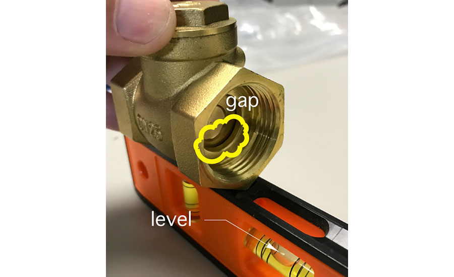
Figure 1 is a photo I took of an inexpensive brass swing check purchased through a major online source.
Notice that even when the valve is installed in a level upright position, the disc is not closing against its seat. The gap gets even bigger if the pipe happens to slope a couple of degree in the downstream direction of the valve. This gap is literally an “open” invitation for weak but persistent pressure differentials caused by water temperature differences in the system to create reverse flow through the valve.
My suggestion: Use a quality “Y-pattern” swing check in which the seat is at a 45-degree angle to the centerline through the valve. This orientation uses the weight of the disc as an incentive to keep it in contact with its seat, even if the piping is slightly out of level.
Springing into action
I’m also starting to question if the nominal 0.25-0.3 psi forward opening pressure of some spring-loaded check valves is sufficient to stop thermal migration. The situation shown in Figure 2 is an example.
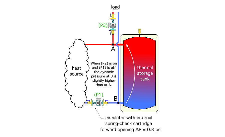
This piping assembly is built around a “2-pipe” thermal storage tank, with the load circuit tied in between the heat source and the tank. Circulator (P1) has a spring-loaded check valve insert and creates flow through the heat source when it’s on. Circulator (P2) creates flow through the load circuit. Both circulators can operate independently.
When circulator (P2) is on and flow returning from the load passes upward through the tank, the dynamic pressure (caused by head loss, not static pressure) at point B is slightly higher than at point A. If this difference is very small, there should be excellent hydraulic separation between circulators (P1) and (P2).
Thus, when (P2) is operating, and (P1) is off, there should be very little tendency for flow to develop in the heat source circuit. The forward opening pressure threshold of the spring-loaded check insert in circulator (P1) should ensure that no flow is induced through (P1) when it’s off and (P2) is on.
But what happens if the pressure drop between points B and A exceeds the nominal 0.25 to 0.3 psi forward opening pressure of a typical spring check cartridge in circulator (P1)?
Answer: Flow will be induced through the heat source circuit when (P1) if off and (P2) is on. This flow causes unnecessary heat loss from the system by allowing heated water to use the inactive heat source as a heat dissipater. Any induced flow also allows some of the water returning from the load to avoid flowing through the thermal storage tank and instead cool down as it flows through the heat source circuit. This flow eventually mixes with the hot water coming from the tank at point A. The resulting “thermal dilution” reduces the water temperature supplied to the load. Double whammy.
The pressure drop created by a few gpm of water flowing through a typical 80-119 gallon buffer tank is extremely low. But the headers connecting the tank to the tees at point A and B add some pressure drop. The closer points A and B are to the tank — and the larger the diameter of the headers — the lower this pressure drop should be.
Unfortunately, I don’t know of any way to accurately predict the pressure drop between points B and A. It might be under 0.3 psi on some systems and just over that threshold on others. Thus, it’s not possible to know for sure if the spring-loaded check cartridge in circulator (P1) is sufficient to stop flow migration through the heat source when (P1) is off and (P2) is on. I’ve seen this flow occur. Either the spring check insert wasn’t working properly, or the pressure drop between points B and A was more than the spring check insert could hold back. This needs to be prevented.
Possible solutions
Spring-loaded check cartridges are available with higher forward opening pressure. For example, cartridges are available with 1.2 psi forward opening pressure rather than 0.3 psi. Again, it’s hard to know exactly what forward opening pressure would be sufficient to stop heat flow though the heat source circuit in Figure 2 when (P2) is on and (P1) is off while avoiding an excessive pressure differential across the spring check insert that wastes head energy and, thus, reduces flow rate. Based on what I’ve observed, I think it needs to be higher than 0.3 psi. It’s a situation that I would welcome the industry — especially manufacturers who supply spring check inserts with their circulators — to research further.
I’ve also found that mounting bodies that can be easily opened to insert spring check cartridges with higher opening pressure thresholds aren’t available in pipe sizes over 1”. The check cartridges are available in larger sizes, but unless you have something to mount them in, really aren’t of any use. Anybody interested? If so, how about offering brass or stainless steel housings for spring check cartridges that can connect to 1.25”, 1.5” and 2” pipe sizes?
Another option is to eliminate reliance on spring-loaded check valves and instead use a motorized ball valve that only opens when the circulator in the circuit is on and is held closed by a spring-return actuator at other times. The closing power of a good spring-loaded actuator is substantial, and should ensure that the flow path through circulator (P1) is blocked against forward or reverse flow whenever (P1) is off.
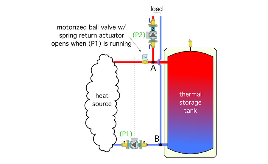
This is how I’m currently detailing systems using “two-pipe” buffer tanks (see Figure 3). If you use this detail, make sure that there’s an unblocked pipe path between the heat source circuit and the system’s expansion tank so that pressures due to water temperature changes can equalize.
Soften the turbulence
A final bit of advice regarding all check valves: Always mount them with at least 12 pipe diameters of straight pipe upstream of the valve. This calms the turbulence produced by other components such as circulators, elbows, tees, strainers, etc. that may be upstream of the check valve and reduces the potential for the disc of the valve to rattle against its seat. I’ve seen this happen on several systems. It’s annoying and expensive to correct. Do it right with some straight pipe.
This article was originally titled “Unexpected results” in the September 2017 print edition of Plumbing & Mechanical.
To read Siegenthaler’s article “Unexpected results” in pdf form, please see here.
Looking for a reprint of this article?
From high-res PDFs to custom plaques, order your copy today!


