Practice good sensor-ship
Give your temperature controllers 20/20 vision.

Figure 1 shows a temperature versus resistance chart for a common 10K NTC thermistor sensor that’s commonly used in the hydronics industry. Photo credit: John Siegenthaler

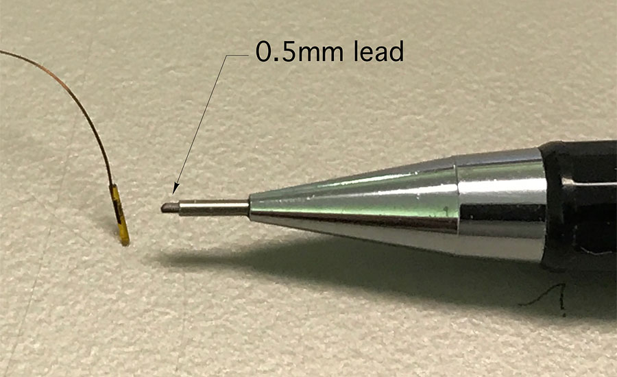
Figure 2 shows just how small some thermistor beads are. Photo credit: John Siegenthaler

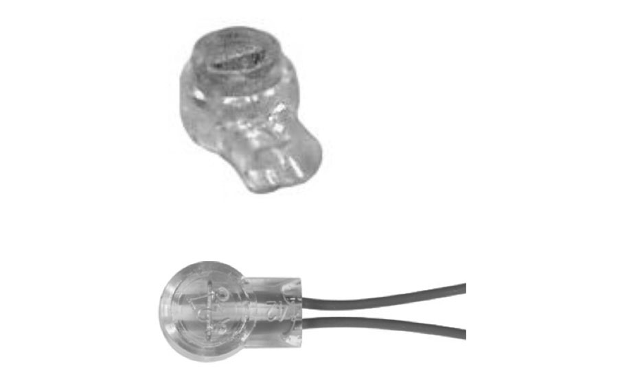
If the joint has to be outside, make it with the gel-fired compression connectors used for exterior telephone wiring connections. An example of such a connector is shown in Figure 3. Photo credit: John Siegenthaler
If the sensors are improperly mounted, the temperature the controller detects can be very different from the temperature the sensor was intended to detect. Figure 4 shows an example. Photo credit: John Siegenthaler

Photo credit: John Siegenthaler

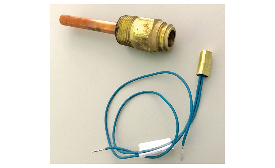
Figure 6 shows a Honeywell 121371B copper sensor well and a 3/8” diameter thermistor sensor that fits properly inside this well, leaving just enough space for thermal paste. Photo credit: John Siegenthaler

This is especially helpful when you need to place a sensor at a specific height within a tank, as shown in Figure 7. Photo credit: John Siegenthaler
Every hydronic system has one or more controllers that measure and respond to temperature. Common examples are temperature set point controllers, outdoor reset controllers, mixing controllers and differential temperature controllers.
Most of these devices use thermistor sensors — or, more specifically, negative temperature coefficient (NTC) thermistor sensors. These solid-state devices decrease their electrical resistance as their temperature increases and vice versa.
Figure 1 shows a temperature versus resistance chart for a common 10K NTC thermistor sensor that’s commonly used in the hydronics industry. The 10K designation indicates the sensors resistance of 10,000 ohms at 77° F (25° C).
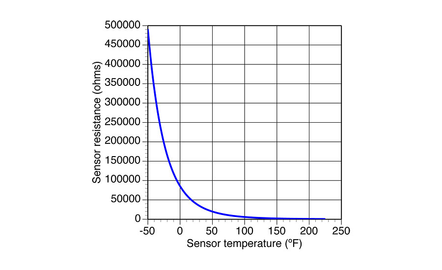
The relationship between the sensor’s temperature and its electrical resistance is not linear. Changes in resistance are much more pronounced at low temperatures. Even so, this relationship between temperature and resistance is very repeatable. Modern digital HVAC controllers can easily translate the electrical resistance of the sensor circuit into an inferred temperature value based on a known and repeatable curve, such as shown in Figure 1.
The type of thermistor sensor used in most HVAC applications consists of a small sold state thermistor bead, an enclosure and lead wires. Thermistor beads can be very small and have very fine attached wires. Figure 2 shows just how small some thermistor beads are.
Tiny thermistor beads with fine wires don’t lend themselves to the handling and placements required in HVAC applications. The solution is to encapsulate the bead in an enclosure that can withstand more physical force and connect it to lead wires rugged enough for installers. During manufacturing, the lead wires are soldered to the thermistor bead (or a tiny circuit board holding the bead). This assembly is then inserted into the enclosure, and a potting material is poured in to permanently seal it in place and protect it against moisture.
Sensor enclosures are made of a highly conductive metal such as copper, brass or stainless steel. The high conductivity minimizes the difference between the temperature of the surface the sensor is mounted to and the temperature at the thermistor bead. For most heating or cooling system control applications, this temperature difference is tiny and of no concern.
Most thermistor sensors used in hydronic systems have lead wires that aren’t long enough to reach from the installed location of the sensor to the controller. A cable must be use to complete the circuit between the sensor and controller. The sensor and cable combined forms the sensor circuit, and the resistance of the sensor circuit is what the controller “feels.” Anything that adds significant resistance to this circuit makes the controller think the temperature at the controller is lower than it actually is.
Designers should verify the minimum wire size (or largest American wire gauge, or AWG, number) that the controller manufacturer allows for connecting the sensor to the controller. Also verify the maximum sensor cable length.
I prefer nothing smaller than 18 AWG copper wire for 10K thermistor sensors. That wiring has a resistance of 0.0064 ohms per foot. If a sensor were located 250 feet from the controller, it would require about 500 feet of sensor wire. The total resistance of that wire would be about 3.2 ohms. This would add to the resistance of the sensor itself. For a 10K thermistor at 77° F, the cable would only represent 0.03% of the circuit resistance. It would have no significant effect on the operating of a hydronic system.
Smaller diameter wires (with large AWGs) have higher resistances. For example, the resistance of 24 AWG copper wire is about four times more than 18 AWG copper. It’s also more fragile.
The bond between the sensor lead wires and the sensor cable can add significant resistance to the circuit. One situation where this becomes an issue is where sensor lead wires are connected to cables using standard wire nuts and then exposed to moisture. The moisture can collect within the wire nut and cause corrosion at the junction.
Over time, this increases the resistance of the sensor circuit and fools the controller into thinking the sensor temperature is lower than it actually is. This was a common problem with early-generation solar thermal systems where the wire nuts connecting the sensor lead to the cable were exposed to weather.
If you need to join the leads from exterior located thermistor sensors to a cable, make every effort to locate the joint inside and where it’s accessible. If the joint has to be outside, make it with the gel-fired compression connectors used for exterior telephone wiring connections. An example of such a connector is shown in Figure 3. The gel inside these connectors provides a waterproof seal of the electrical bond.
Sensor circuits can also be affected by strong electromagnetic fields. Such fields can induce currents in sensor cables that inevitably will throw off the controller. To reduce the chances of such interference, never run sensor cable next to or in the same conduit as AC wiring.
 If the sensors must be installed near devices such as large motors, light ballasts or large transformers, use cabling with twisted pair wires or, even better, shielded cable. The latter has a metal foil layer between the exterior insulation and internal conductors. One end of this metal foil should be fastened to an electrical ground. The other end of the foil should be electrically isolated and not fastened to anything.
Mount up
Most current-generation digital temperature controllers offer excellent accuracy and reliability. However, these controllers can only respond to the information they receive from their sensor(s). If the sensors are improperly mounted, the temperature the controller detects can be very different from the temperature the sensor was intended to detect.
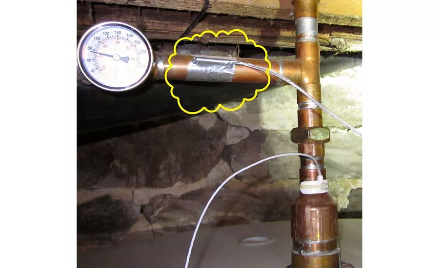
Figure 4 shows an example. The temperature sensor seen in the yellow cloud is taped to the copper tubing. Its intended purpose was to detect the water temperature in the upper portion of a thermal storage tank seen in the lower portion of the photo. Instead, it’s detecting a temperature somewhere between that of the tube surface and the surrounding air temperature.
 This sensor is connected to a controller that turns a boiler on and off, supposedly based on the temperature in the upper portion of the thermal storage tank. Needless to say, that boiler was not operating as expected.
When the temperature of fluids contained in tanks is to be measured, the sensor should be mounted in a well that’s threaded into an appropriate tank tapping. Prior to inserting the sensor, a small amount of thermal paste should be injected into the end of the well using a plastic syringe. The sensor body should also get coated with thermal paste as in Figure 5.
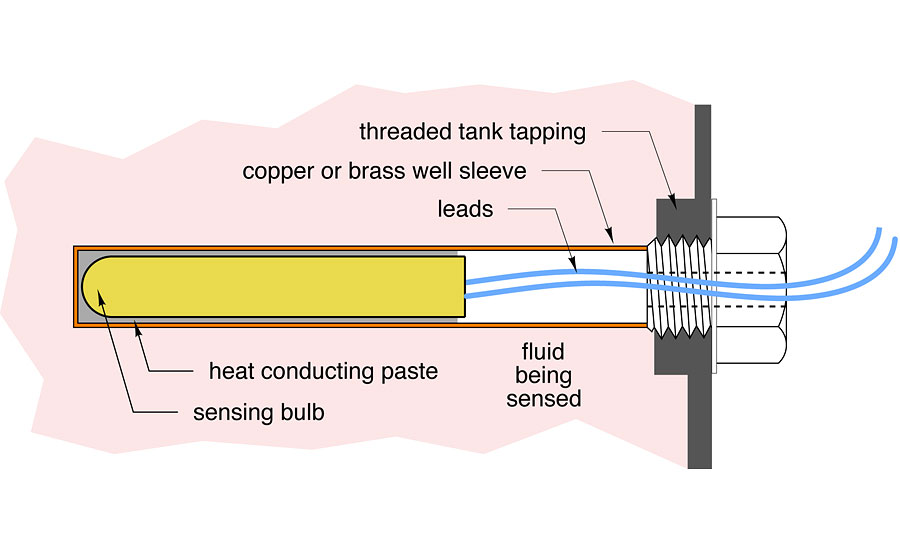 The objective is to completely fill the gap between the sensor body and inside surface of the well with thermal paste. Doing so improves conductivity and reduces the time lag between changes in water temperature — and when that change is detected by the sensor.
Figure 6 shows a Honeywell 121371B copper sensor well and a 3/8” diameter thermistor sensor that fits properly inside this well, leaving just enough space for thermal paste. These well are available in either 1/2” or 3/4” MPT threads. Many thermal storage tanks have 1/2” or 3/4” FPT threaded tappings to receive these wells. When this type of well needs to go into tanks with 1.5” or 2” FPT tappings, use a brass bushing for the size transition.
 It’s also possible to mount sensors to the surface of copper tubing. Some sensors have a small concave channel on their housing that allows that housing to “saddle” the pipe and have more contact surface area. Sensors mounted to copper tubing should be secured with two nylon pull ties that are rated to handle the temperature the pipe may experience. Inferior pull ties will harden over time and break.
A small dab of thermal paste should be placed between the sensor and pipe surface. After the sensor is secured with the pull ties, a nominal 6” length of insulation should be placed and centered over the sensor. The insulation sleeve should be sealed from air penetration at both ends. I like to use a high-grade electrical tape for this sealing.
It’s also possible to make a sensor well using copper tubing closed at the end with a soldered cap. The length of the well is whatever you need. This is especially helpful when you need to place a sensor at a specific height within a tank, as shown in Figure 7.
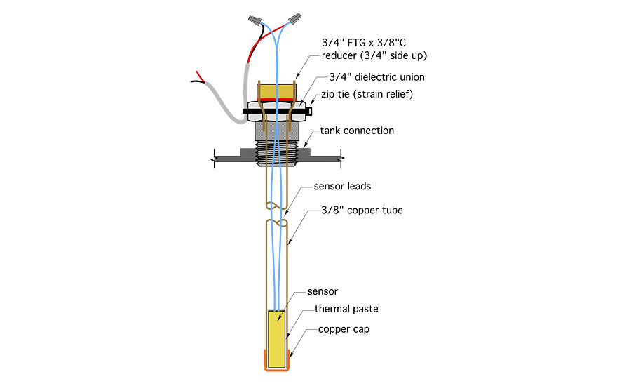
For example, a 3/8” type M copper tube has an inside diameter of 0.450 inches. A 3/8” diameter sensor housing fits into this tubing, leaving about 1/32” gap between the sensor house an inside of the tube. This gap should be filled with thermal paste. The 3/8” tube can be sealed to a 3/4” MPT adapter using a brass slip bushing.
If you’re planning a long sensor well inserted through a connection at the top of the tank, be sure there’s adequate head room to insert it after the tank is in place. If there isn’t, you’ll need to insert the well before the tank is rotated into its vertical position.
It’s also important to provide strain relief for the wires connecting the sensor leads to the cable. A temperature-rated zip tie holding the sensor cable to the exterior portion of the well, or other nearby solid surface, is generally acceptable.
Finally, be sure you label and tag every sensor in the system. Label the sensors on the piping and electrical schematics as you design the system and attach tags to the sensors as they are installed.
Sensors are the eyes of temperature controllers; those controllers can only react to what they see. Careful sensor placement and mounting is critical to giving those controllers 20/20 vision.
To read Siegenthaler’s article “Good sensor-ship” in pdf form, please see here.
Looking for a reprint of this article?
From high-res PDFs to custom plaques, order your copy today!


