Continuous circulation in floor-heating circuits

Figure 1. The most popular approaches are variable-speed injection mixing, three-way motorized mixing valves, and four-way motorized mixing valves. These options are shown in Figure 1. Photo credit: John Siegenthaler

Figure 2. In multi-zone systems using a common supply water temperature, constant circulation can be facilitated using motorized diverter valves, as shown in Figure 2. Photo credit: John Siegenthaler
Most hydronic systems stop water flowing through their distribution system, or portions of multiple zone systems, when the thermostat(s) stop calling for heat. It’s a simple approach but not the only way to limit heat output. It also has an Achilles heel.
Consider this scenario: The thermostat in a light commercial building with hydronic baseboard heating is normally set for 68° F. When everyone leaves at 5 p.m., the boss sets the thermostat to its lowest setting, say 50°. He does this because of a mistaken belief that the lower he sets the thermostat the more money he’s going to save by not burning fuel overnight. Water flowing in the system stops the moment the thermostat is set back.
During the night, the outdoor temperature drops to minus 15°. An air leak at the exterior wall allows a small but persistent stream of super cold air to waft across the 1/2-inch copper piping in the baseboard mounted against that exterior wall. As the night progresses, the air temperature at the thermostat slowly decreases from 68° down to 60° by 6 a.m.
The thermostat is still not calling for heat, and you probably know what comes next — a hard freeze in the baseboard element near the air leak, a crack in the pipe or a fitting, and an automatic fill valve that happily feeds gallon after gallon into the system as water escapes from the ruptured pipe and spreads out across the floor. If you’ve been involved with hydronic systems in cold climates, you’ve had this dream (or real-life experience).
Now imagine a similar thermostat manipulation in a system with a heated garage floor. Water in embedded tubing that runs just inside the overhead door stops for several hours during sub-zero outdoor temperatures. Subfreezing air leaks under the marginal seal at the bottom of the overhead door. Heat also conducts through the slab under the door because there’s no thermal break, just a slab joint, between the floor and the outdoor concrete apron. An ice plug eventually forms inside the tubing.
When the thermostat is turned back up the next morning, the outer portion of the floor slab remains cold because the ice plug blocks all flow through the circuit serving that area. The fun begins when someone figures out what’s happened and tries to remedy it by propping up three hair dryers to blow warm air across the slab. Who knows, after several hours they might get lucky. If not, they should check the weather forecast and hope that a few days with above-freezing temperatures are coming.
Just ‘Glyc It’
About now many of you are wondering, why not just put antifreeze in those systems and be done with it? Well, that is one approach, but it also comes with some baggage.
Using antifreeze can add significant cost to the system. The fluid alone adds several hundred dollars to the cost of a floor heating system in a 10,000-square-foot facility. There’s also added cost for larger expansion tanks, larger circulators, a glycol feeder system, and annual checks and adjustments to the fluid chemistry.
Another cost often not considered is the increased power input to the circulator required to provide equal heat transfer rates. In theory, the pumping power input required for a 50% solution of propylene glycol is about 66% more than when water is used. Over the life of the system, that can add hundreds if not thousands of dollars in added electrical energy use. It also increases utility demand charges in commercial or industrial facilities.
If one assumes the scenario of an electrical outage that might last for several days (even weeks) during very cold weather, antifreeze is a failsafe option. However, many of the commercial and municipal garage projects we’ve been involved with over the last few years have been opting for on-site emergency generators to get that facility back online during such an outage.
Although most of these generators have sufficient power to operate gas- or oil-fired boilers, they may not have capacity to run heat pumps or electric boilers.
There’s also the argument that a boiler issue that requires several days to service could lead to a freeze-up in systems without antifreeze, even if electrical power is available.
The alternative
There’s another way to dramatically improve the ability of a high mass slab heating system to survive many cold winter days without heat input: Instead of adding antifreeze to the system, or stopping water flow when the thermostat is satisfied, design the system for constant circulation.
Constant circulation allows heat that is stored in the interior areas of the slab to be relocated to the high-heat-loss perimeter areas, such as just inside overhead doors in a garage-type facility. Think of the circulating water as Robin Hood — it steals from the areas rich in heat storage and gives to the areas in need.
The high thermal mass of a floor slab can keep sufficient heat in all parts of the circuit to prevent freezing for several days, even in cold weather. I’ve witnessed this firsthand.
A building for which we designed a floor heating system back in the 1980s experienced a roof collapse due to heavy snow loading. The slab was directly exposed to sub-freezing outdoor temperatures for several days as the remnants of the building were removed and a new building constructed.
The circulators in the mechanical room were not affected and maintained flow through the circuits in the exposed slab 24/7 without further heat input. No freeze damage occurred, and that system is still working fine. This certainly wasn’t a planned test for constant circulation, but it made a big impression on me.
The details
In systems where all floor heating is controlled as a single zone, continuous circulation is easily accomplished using one of several mixing methods. The most popular approaches are variable-speed injection mixing, three-way motorized mixing valves, and four-way motorized mixing valves. These options are shown in Figure 1.
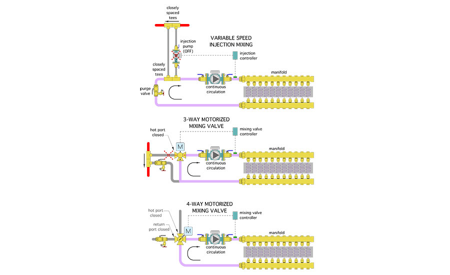
When the thermostat is satisfied, all of these mixing assemblies prevent hot water from the heat source from entering the recirculating distribution system. The variable-speed injection pump stops. The two pairs of closely spaced tees provide hydraulic isolation of the injection mixing assembly, and the spring-loaded check valve in the injection circulator prevents heat migration. The three- and four-way mixing valves simply close their hot water port.
One way or the other
In multi-zone systems using a common supply water temperature, constant circulation can be facilitated using motorized diverter valves, as shown in Figure 2.
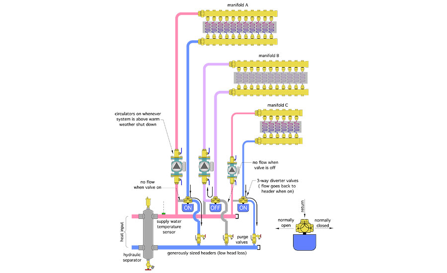
These three-way valves are for diverting, not mixing. They only have two operating states — all flow returning from the floor circuits within a zone either goes to the return header or gets routed back through the circulator.
When the thermostat for the zone is not calling for heat, the diverter valve is off and flow returning from the floor circuits makes a U-turn and goes back through the circulator to the supply manifold. This is shown for manifold station B in Figure 2.
When a zone thermostat calls for heating, the diverter valve is powered on. Flow returning from the floor circuits goes back to the return header, just as if the three-way diverter valve wasn’t there.
The diverter valves can be wired to a multi-zone relay center that provides either 24 VAC output for typical two-way zone valves, or 120 VAC output for zone circulators. Just match the operating voltage of the actuator on the diverter valve to the output provided by the multi-zone relay center.
All zone circulators operate whenever the system is not in warm-weather shutdown mode.
The hydraulic separator and generously sized headers provide hydraulic separation between the zone circulators and the circulator(s) associated with the heat source. It also provides air and dirt separation for the system.
If the water temperature on the load side of the hydraulic separator is regulated based on outdoor reset control, the diverter valves will be on most of the time. Assuming that the outdoor reset controls are properly set, the diverter valves would only close when the thermostat is satisfied due to internal heat gains. This is not a problem and should yield a consistent matching between the load and heat delivery.
Motorized three-way ball valves with high Cv values are ideal for the diverting function in these systems. Don’t use valves with Cv values lower than the flow rate (in gpm) passing through them.
In addition to municipal garages, continuous circulation and floor heating can work hand-in-hand in fire stations, ambulance garages, aircraft hangers, vehicle service buildings, and loading dock areas in warehouses. It can also be used in residential projects with heated slab floors.
Use it when appropriate.
To read Siegenthaler's article in pdf form, please see here.
Looking for a reprint of this article?
From high-res PDFs to custom plaques, order your copy today!


