Taking the easy path
The Glitch & The Fix, February 2017
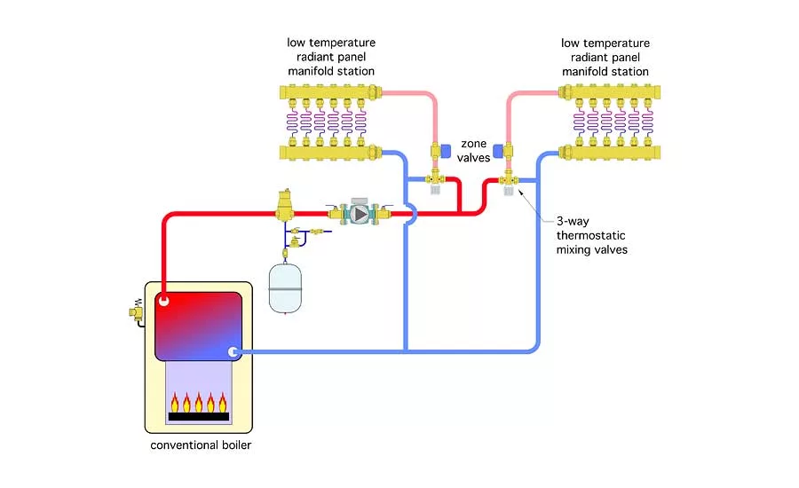
The Glitch drawing: It represents piping up a two-zone, low-temperature radiant floor heating system to a conventional gas-fired boiler.
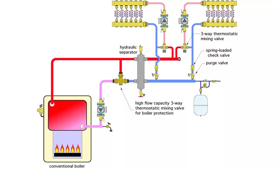
The Fix: The fix is to install a circulator between each mixing valve and its associated manifold station.
The Glitch
An installer pipes up a two-zone, low-temperature radiant floor heating system to a conventional gas-fired boiler, as shown below. Zone valves are installed so that each zone can operate independently. Can you identify at least four errors in this design?
The Fix:
1. Whenever there’s a mixing valve in a hydronic distribution system there has to be a circulator between that mixing valve and the heat emitters. This is not the case in the glitch drawing. Remember: When flow exits a circulator all it “cares about” is getting back to the inlet of that circulator. In the glitch drawing there is virtually no “incentive” for flow to pass through the radiant panel manifold stations, even when the zone valves are open. Instead, it takes the short cut from the hot port to the cold port of the thermostatic mixing valves. This is sure to lead to an underheating problem.
The fix is to install a circulator between each mixing valve and its associated manifold station as shown in Figure 2 (The Fix drawing above). Eliminate the zone valves. The hydraulic separator is also used to minimize interaction between these new circulators, as well as between them and the boiler circulator. It also provides high efficiency air and dirt separation for the system.
2. There is nothing to prevent sustained flue gas condensation from forming within the conventional boiler. There are several ways to fix this, each of which measures the water temperature entering the boiler and reacts to it. One of the simplest approach is to install a high flow capacity 3-way thermostatic mixing valve as shown in Figure 2.
This valve will always modulate in an attempt to keep the boiler inlet temperature at or above 130 ºF, which is generally high enough to prevent sustained flue gas condensation.
3. Because each of the manifold stations now has its own circulator, each can operate as a separate zone. However, this requires preventing of flow reversal through the inactive zone when the other zone is operating. A 3-way thermostatic valve cannot provide flow reversal protection, because under certain conditions flow can move directly between the hot and cold ports of the valve. This potential flow short circuiting also prevents a spring-loaded check valve within each of the new circulators from ensuring there is no flow reversal. The solution is to install a spring-loaded check valve near the end of each branch circuit. Provide at least 12 pipe diameters of straight pipe upstream of this check valve to minimize turbulence and possible rattling of the valve’s internal disc.
4. Finally, the system in figure 1 lack any means of forced-water purging. Two purging valves, one in each branch circuit, have been installed in the system of Figure 2 to handle this task.
This article was originally titled “Taking the easy path” in the February 2017 print edition of Plumbing & Mechanical.
Looking for a reprint of this article?
From high-res PDFs to custom plaques, order your copy today!


.jpg")