Selecting the correct temperature and pressure relief valve
The safer choice.
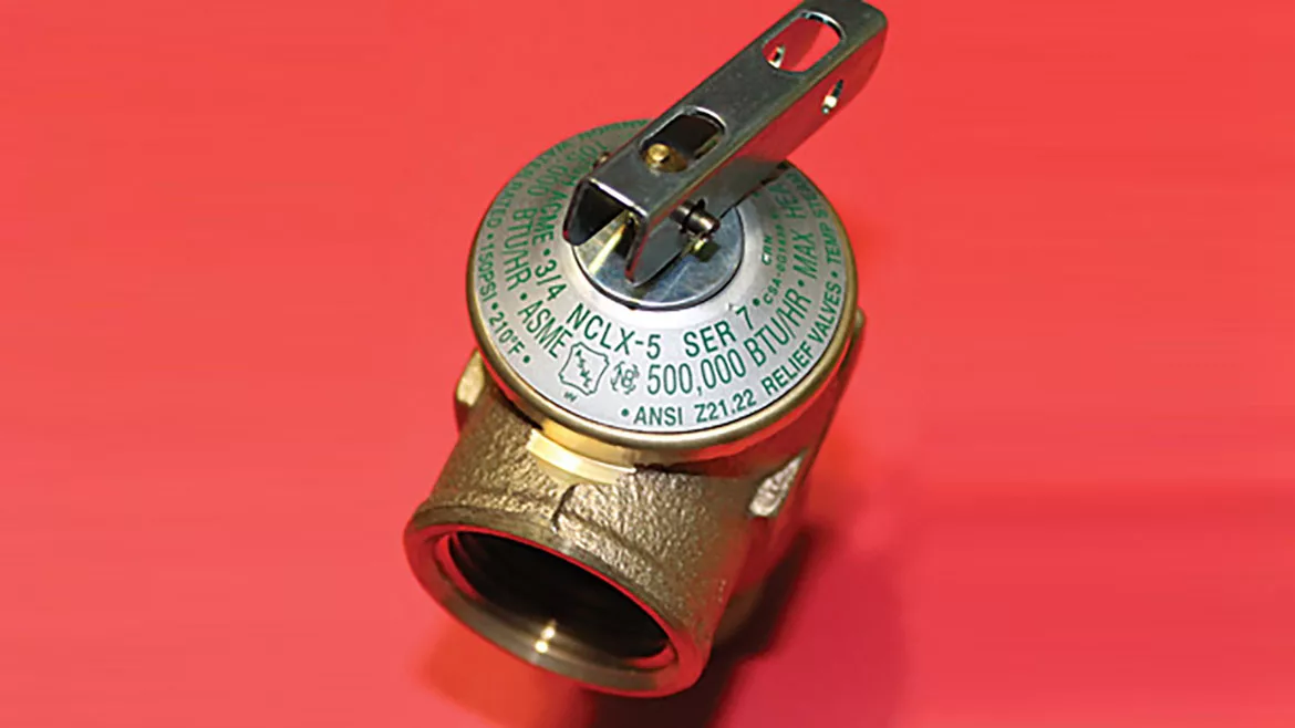
A typical temperature and pressure relief valve. Photo credit: Don Jones
The code of construction of the vessel itself can play a key role in choosing the correct valve capacity. Unfortunately, the code of construction criteria is unknown to many and overlooked by others.
As the name indicates, T&P relief valves are designed to protect water heaters and hot-water storage vessels against excess temperature and excess pressure. Most valves are rated at 150 psi and 210° F, but their capacity ratings vary greatly. Sometimes, an additional T&P relief valve with a lower temperature and pressure rating (typically 180° and 100 psi) is installed in a plastic hot-water distribution system to protect the piping system itself. A T&P relief valve is, in essence, a dual device because it meets the code requirements of an individual temperature relief valve and an individual pressure relief valve.
The temperature function of the valve is controlled by an internal thermostatic element. At 210°, the internal expansion within the probe causes a piston to push against the valve’s disk. The spring is overpowered and compressed, and the water escapes between the disc and seat. The extremely hot water within the tank is forced out under pressure as cold water replenishes the discharge. The cold water rushing into the vessel lowers the water temperature, and when the temperature drops back below 210°, the valve is reseated.
The pressure function of the valve also is controlled by the spring, disc and seat. When the pressure exceeds the valve’s pressure rating, the water pressure overcomes the spring. The spring is compressed (just like a typical pressure-only relief valve) and the water escapes between the disc and seat.
It is important to note that when the valve is weeping or dripping, the cause is usually excessive pressure. Many times this is caused by thermal expansion. A T&P relief valve is not designed to nor should it be used to continuously control thermal expansion within a closed system. Thermal expansion of hot water within a closed system should be controlled with the installation of an approved expansion tank or by other means permitted by local code.
Dripping may continue because of debris within the valve, such as a build-up of calcium in the seat, and over time, large mineral deposits can make the valve ineffective. When a valve is discharging a large quantity of water, the cause is almost always excessive temperature.
Code and capacity
The only way to determine the maximum allowable working pressure of a vessel is to read the nameplate that is attached to it. The pressure on the valve’s tag must be compared to the pressure on the vessel’s nameplate. The pressure rating of the relief valve must be equal to or less than the MAWP of the vessel. Most water heaters have an MAWP of 150 psi; however, some are rated higher, typically 160 psi. Some storage vessels have a lower pressure rating; they are commonly rated 125 psi.
Another factor in determining the pressure rating of the T&P relief valve is the code itself. Model codes require the T&P relief valve be set no higher than 150 psi. Therefore, a water heater with a MAWP of 160 psi still requires a T&P relief valve set at 150 psi, even though the vessel is designed and built to withstand a higher pressure.
The relieving capacity of the valve must be equal to or greater than the Btu/hr. of the vessel. The thermal capacity of the water heater can be found on its nameplate along with the MAWP. The confusion in choosing the correct T&P relief valve resides on the relief valve’s nametag itself. T&P relief valves display two relieving capacity ratings. One is the American Society of Mechanical Engineers/National Board of Boiler and Pressure Vessel Inspectors rating, and the other is the Canadian Standards Association/American National Standards Institute Z21.22 rating.
The relieving capacity of the valve’s ASME/NB rating is established by Section IV, Part HG of the “ASME Boiler and Pressure Vessel Code.” The code reads, “Capacity certification tests of safety relief valves for water heating and hot-water supply boilers shall be conducted at 110% of the pressure for which the valve is set to operate.” So the capacity of a T&P relief valve set at 150 psi is based on its vessel pressurized to 165 psi.
The ASME/NB relieving capacity rating is more lenient than the CSA rating. The CSA rating is based on 15 psi of steam pressure, so the CSA rating will always be lower and, therefore, more stringent than the ASME/NB rating. ASME HLW water heaters are built to a more stringent code of construction than ANSI Z21 water heaters. The use of a valve’s ASME/NB capacity rating to protect an ANSI-built vessel could present a potentially dangerous condition.
Chapter 5, Section 504.4 of the 2012 International Plumbing Code specifically requires relief valves to conform to the Z21.22 standard; the code is very concise. Some of the other model codes are not as clear as the IPC. Section 504 of the Uniform Plumbing Code only references an approved, listed device installed in accordance with the listing and the manufacturer’s installation instructions; however, the Z21.22 standard is included in Table 1401.1.
While the 2012 National Standard Plumbing Code makes no distinction between the use of the ASME/NB and CSA capacity ratings, the 2015 NSPC will limit the use of the ASME/NB relieving capacity ratings to ASME vessels only.
If permitted by the local adopted code, AMSE/NB relieving capacities should only be considered for ASME vessels. The more restrictive CSA relieving capacities are always the safer choice.
HELPFUL LINKS:
Looking for a reprint of this article?
From high-res PDFs to custom plaques, order your copy today!


.jpg")