Full Circle
Will low head loss boilers make a come back?
Some of you have probably been installing hydronic heating for 30 years or more. Consider yourselves lucky to have witnessed not only a rebirth of the industry in North America, but also a steady refinement of technology.
I think it’s safe to say that no one who falls into this vintage is currently installing systems the same as they did 30 years ago. During the last three decades, there's been a deluge of new hardware for almost every aspect of the system from which to choose. Design concepts and objectives have also changed over this time.
The changes we’ve made and continue to make in system design are influenced by complex interactions - the people and companies we know, favorite technical concepts, cost-saving opportunities, energy-saving opportunities, what we read in trade magazines, and what we observe others doing. This holds true at all levels of the industry, from installer right up through the manufacturer.
Thinking that we’ll someday arrive at the ultimate design concept and hardware configuration implies limits that few of us would be willing to accept. Although what you might be doing today is “state-of-the-art,” it will surely loose that title, perhaps even by next year.
Without this continuous movement, our industry would eventually cease to exist, especially as competing technologies constantly offer up a challenge. If you don’t believe this, do some research on the state of hydronic radiant panel heating in North America a mere 30 years ago. If PEX tubing hadn’t shown up to breathe new life into the concept, it was all but dead.
Sometimes our industry goes down technological paths that later prove less than optimal. Of course, no one realizes this until looking back. Sometimes we also find that old concepts aren’t necessarily dead, even though they’ve been mothballed for a while as other “contemporary” approaches enjoy their time in the spotlight.
This month I want to look at a situation in which a technical detail our industry relied on extensively 30 years ago, one that some might consider “over the hill” as evidenced by today’s standard practice, has the potential to re-emerge and move the industry forward in the process.
A state-of-the-art hydronic heating system circa 1978 was usually built around a cast-iron or steel boiler connected to a masonry chimney. A site-built black iron header came off the top or side of that boiler. The tees it contained ran off to two, or maybe in a big house, three zones of series-connected finned-tube baseboard. Those zones returned to a corresponding number of zone valves mounted on the return header. The header connected to a three-piece circulator, and then to the boiler’s return connection. On the side or front of the boiler was a tankless coil for domestic water heating.
One of the nice features of this system - though not fully appreciated at the time - was the low-flow resistance of the boiler and header piping. This characteristic allowed multiple zones to operate essentially as if they were stand-alone circuits. When a given circuit turned on or off, there was minimal affect on other circuits. Things were pretty simple.
This combination certainly reduced the size and weight of boilers, as well as their warm-up time. In most cases, it also introduced a very different flow characteristic to the boiler, that of high head loss relative to traditional boilers.
One early example was the GlowCore boiler, which had a coiled copper heat exchanger surrounding a cylindrical burner. The pressure drop of the tightly coiled heat exchanger was much greater than that of other boilers being installed at the time.
Many installers overlooked the consequences of this characteristic and installed the GlowCore boiler just like a cast-iron boiler, with all system flow piped through the boiler. This often bottlenecked the system, leading to inadequate heat delivery. The opposite situation also occurred when zone valves were used. Flow starvation through the boiler’s low-mass heat exchanger under low load conditions lead to damaged heat exchangers.
Some of you probably remember the reputation that GlowCore boilers eventually got. A reputation that in hind site was largely the result of improper application and failure to recognize that the industry had reached the point where not all boilers could be piped the same.
Eventually the industry learned to connect compact condensing boilers into the system as a secondary circuit with its own dedicated circulator. Today this is a common detail in installation schematics for such boilers. This realization even led to the development and use of new devices such as hydraulic separators.

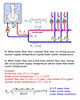
In some cases, the hydraulic separation of a boiler from the distribution system also creates a deviation between boiler outlet temperature and the temperature of water supplied to the distribution system as shown in Figure 1.
Some boiler operating controls use an externally mounted sensor to measure the temperature of water supplied to the distribution system; others do not. Those that don’t are often set to produce an outlet temperature slightly higher than that needed by the distribution system. This is done in an attempt to keep supply temperature close to what’s needed after the flows have mixed at the point of hydraulic separation. This also means the boiler operates at a temperature higher than necessary and thus at a slightly reduced efficiency.
There are only two ways that I’m aware of to ensure that boiler modulation is controlled based on the supply temperature to the distribution system:
Measure this temperature and modulate the burner based on it (e.g.,
using a system supply temperature sensor mounted downstream of the point of
hydraulic separation).
Pass all system flow through boiler and eliminate the hydraulic
separation point and its associated mixing.
Either of these approaches is viable, but the option of passing all flow through the mod/con boiler offers the added benefit of eliminating the boiler circulator, its associated piping, and the life-cycle operating cost of this circulator.
One might argue that the electrical energy consumption associated with pushing flow through a boiler will occur regardless of whether that power is fed into a separate boiler circulator or through the system circulator. This is not necessarily true.
Although the mechanical power to push flow through the boiler at a given flow rate and associated pressure drop is the same, the corresponding electrical power required depends on the wire-to-water efficiency of the circulator supplying the mechanical power. The higher this efficiency, the lower the electrical power requirement. Thus, if the system circulator can operate at a higher wire-to-water efficiency than that of a small wet-rotor boiler circulator, it provides a slight advantage.
This scenario is poised to become more common as ECM-based circulators, with wire-to-water efficiencies about double those of current PSC-based wet-rotor circulators, are increasingly used in hydronic distribution systems.
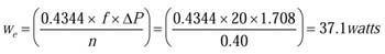
Here’s an example of the potential savings for a small residential system:
Assume a boiler has a head loss of 4 feet (pressure drop = 1.708 psi) at a corresponding flow rate of 20 gpm. The estimated electrical power to provide this condition using a small wet-rotor circulator with PSC motor and 22 percent wire-to-water efficiency is:
 If
this same mechanical energy were supplied from an ECM-based distribution circulator
operating at 40 percent wire-to-water efficiency, the electrical wattage drops
to:
If
this same mechanical energy were supplied from an ECM-based distribution circulator
operating at 40 percent wire-to-water efficiency, the electrical wattage drops
to:
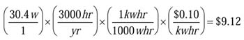 Assuming the boiler operates 3,000 hours per year and
that electricity costs 10 cents per kwhr, the first-year savings would be as
follows (based on the difference in operating wattage):
Assuming the boiler operates 3,000 hours per year and
that electricity costs 10 cents per kwhr, the first-year savings would be as
follows (based on the difference in operating wattage):
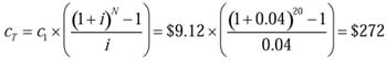 Over
20 years, with electricity inflating at 4 percent per year, this works out to a
savings of:
Over
20 years, with electricity inflating at 4 percent per year, this works out to a
savings of:
Keep in mind that this is in addition to the cost savings from not installing a separate boiler circulator and associated piping. This would easily add up to $400 or more in additional savings in a small residential system.
There are some mod/con boilers available in North America capable of “pump through” application. The key is minimizing head loss through the boiler.
Although there is no threshold that determines a go/no go decision for pumping through application, I suggest that the boiler should develop a loss no greater than 4 feet of head while passing full design flow rate through its heat exchanger. It’s also beneficial if the boiler’s heat exchanger can operate with a temperature rise of perhaps 30 degrees F or more under design load. Higher delta T means lower flow rates, lower head loss and, for a given supply temperature, lower return temperatures. The latter enhances flue gas condensation and boosts efficiency.
Will the future of mod/con boilers be “pump through” design? Will we eventually come back to systems as simple as a single-system pump (ECM-based variable speed) pushing flow through the boiler and then on to a distribution system zoned using zone valves or TRVs? Such an approach surely offers simplicity. It also reduces both installation and operating cost, as well as eliminates temperature variation between the boiler outlet and system supply. These characteristics are beneficial to both the customer and the installer.
Some of you have probably been installing hydronic heating for 30 years or more. Consider yourselves lucky to have witnessed not only a rebirth of the industry in North America, but also a steady refinement of technology.
I think it’s safe to say that no one who falls into this vintage is currently installing systems the same as they did 30 years ago. During the last three decades, there's been a deluge of new hardware for almost every aspect of the system from which to choose. Design concepts and objectives have also changed over this time.
The changes we’ve made and continue to make in system design are influenced by complex interactions - the people and companies we know, favorite technical concepts, cost-saving opportunities, energy-saving opportunities, what we read in trade magazines, and what we observe others doing. This holds true at all levels of the industry, from installer right up through the manufacturer.
Thinking that we’ll someday arrive at the ultimate design concept and hardware configuration implies limits that few of us would be willing to accept. Although what you might be doing today is “state-of-the-art,” it will surely loose that title, perhaps even by next year.
Without this continuous movement, our industry would eventually cease to exist, especially as competing technologies constantly offer up a challenge. If you don’t believe this, do some research on the state of hydronic radiant panel heating in North America a mere 30 years ago. If PEX tubing hadn’t shown up to breathe new life into the concept, it was all but dead.
Sometimes our industry goes down technological paths that later prove less than optimal. Of course, no one realizes this until looking back. Sometimes we also find that old concepts aren’t necessarily dead, even though they’ve been mothballed for a while as other “contemporary” approaches enjoy their time in the spotlight.
This month I want to look at a situation in which a technical detail our industry relied on extensively 30 years ago, one that some might consider “over the hill” as evidenced by today’s standard practice, has the potential to re-emerge and move the industry forward in the process.
A state-of-the-art hydronic heating system circa 1978 was usually built around a cast-iron or steel boiler connected to a masonry chimney. A site-built black iron header came off the top or side of that boiler. The tees it contained ran off to two, or maybe in a big house, three zones of series-connected finned-tube baseboard. Those zones returned to a corresponding number of zone valves mounted on the return header. The header connected to a three-piece circulator, and then to the boiler’s return connection. On the side or front of the boiler was a tankless coil for domestic water heating.
One of the nice features of this system - though not fully appreciated at the time - was the low-flow resistance of the boiler and header piping. This characteristic allowed multiple zones to operate essentially as if they were stand-alone circuits. When a given circuit turned on or off, there was minimal affect on other circuits. Things were pretty simple.
Figure 1
Smaller Body, Bigger Head
The push for increased energy efficiency brought with it some radical new ideas about boiler design. A trend developed toward low-mass condensing boilers with heat exchangers made of finned copper tubing or stainless steel.This combination certainly reduced the size and weight of boilers, as well as their warm-up time. In most cases, it also introduced a very different flow characteristic to the boiler, that of high head loss relative to traditional boilers.
One early example was the GlowCore boiler, which had a coiled copper heat exchanger surrounding a cylindrical burner. The pressure drop of the tightly coiled heat exchanger was much greater than that of other boilers being installed at the time.
Many installers overlooked the consequences of this characteristic and installed the GlowCore boiler just like a cast-iron boiler, with all system flow piped through the boiler. This often bottlenecked the system, leading to inadequate heat delivery. The opposite situation also occurred when zone valves were used. Flow starvation through the boiler’s low-mass heat exchanger under low load conditions lead to damaged heat exchangers.
Some of you probably remember the reputation that GlowCore boilers eventually got. A reputation that in hind site was largely the result of improper application and failure to recognize that the industry had reached the point where not all boilers could be piped the same.
Eventually the industry learned to connect compact condensing boilers into the system as a secondary circuit with its own dedicated circulator. Today this is a common detail in installation schematics for such boilers. This realization even led to the development and use of new devices such as hydraulic separators.
Are We There Yet?
Adding a separate circulator, in some cases a high head circulator, solves the issue of providing adequate boiler flow regardless of what’s happening in the distribution system. At the same time, it also adds to both installation and operating cost relative to the older systems, where all flow passed through the boiler.In some cases, the hydraulic separation of a boiler from the distribution system also creates a deviation between boiler outlet temperature and the temperature of water supplied to the distribution system as shown in Figure 1.
Some boiler operating controls use an externally mounted sensor to measure the temperature of water supplied to the distribution system; others do not. Those that don’t are often set to produce an outlet temperature slightly higher than that needed by the distribution system. This is done in an attempt to keep supply temperature close to what’s needed after the flows have mixed at the point of hydraulic separation. This also means the boiler operates at a temperature higher than necessary and thus at a slightly reduced efficiency.
There are only two ways that I’m aware of to ensure that boiler modulation is controlled based on the supply temperature to the distribution system:
Either of these approaches is viable, but the option of passing all flow through the mod/con boiler offers the added benefit of eliminating the boiler circulator, its associated piping, and the life-cycle operating cost of this circulator.
One might argue that the electrical energy consumption associated with pushing flow through a boiler will occur regardless of whether that power is fed into a separate boiler circulator or through the system circulator. This is not necessarily true.
Although the mechanical power to push flow through the boiler at a given flow rate and associated pressure drop is the same, the corresponding electrical power required depends on the wire-to-water efficiency of the circulator supplying the mechanical power. The higher this efficiency, the lower the electrical power requirement. Thus, if the system circulator can operate at a higher wire-to-water efficiency than that of a small wet-rotor boiler circulator, it provides a slight advantage.
This scenario is poised to become more common as ECM-based circulators, with wire-to-water efficiencies about double those of current PSC-based wet-rotor circulators, are increasingly used in hydronic distribution systems.
Here’s an example of the potential savings for a small residential system:
Assume a boiler has a head loss of 4 feet (pressure drop = 1.708 psi) at a corresponding flow rate of 20 gpm. The estimated electrical power to provide this condition using a small wet-rotor circulator with PSC motor and 22 percent wire-to-water efficiency is:
Keep in mind that this is in addition to the cost savings from not installing a separate boiler circulator and associated piping. This would easily add up to $400 or more in additional savings in a small residential system.
There are some mod/con boilers available in North America capable of “pump through” application. The key is minimizing head loss through the boiler.
Although there is no threshold that determines a go/no go decision for pumping through application, I suggest that the boiler should develop a loss no greater than 4 feet of head while passing full design flow rate through its heat exchanger. It’s also beneficial if the boiler’s heat exchanger can operate with a temperature rise of perhaps 30 degrees F or more under design load. Higher delta T means lower flow rates, lower head loss and, for a given supply temperature, lower return temperatures. The latter enhances flue gas condensation and boosts efficiency.
Will the future of mod/con boilers be “pump through” design? Will we eventually come back to systems as simple as a single-system pump (ECM-based variable speed) pushing flow through the boiler and then on to a distribution system zoned using zone valves or TRVs? Such an approach surely offers simplicity. It also reduces both installation and operating cost, as well as eliminates temperature variation between the boiler outlet and system supply. These characteristics are beneficial to both the customer and the installer.
Links
Looking for a reprint of this article?
From high-res PDFs to custom plaques, order your copy today!


