Across The Mains
John Siegenthaler

Prior to the resurgence of interest in primary/secondary piping, most residential and light commercial hydronic systems used piping headers at the boiler as the beginning and ending points for branch circuits. For years the concept was simply to pipe the zone circuits across the headers.
This concept also applies to traditional "two-pipe" distribution systems (Figure 1). A central circulator creates a pressure differential between the hot water supply and return mains. This pressure differential pushes flow through any piping path connected from the supply to the return mains. Adding a branch circuit is simply a matter of connecting "across the mains."
Both of these piping concepts have worked well in the past, and certainly can continue to work well when properly applied in future systems. However, things can go south in a hurry when the concept of connecting across the main is stirred in while attempting to cook up a primary/secondary (P/S) system. The resulting assembly is neither "two-pipe" nor P/S. Instead, the undefined piping aberration becomes the battleground for a war between competing circulators. The water flows in various parts of the system become the refugees in this war. The compromised comfort becomes the collateral damage.

In both systems, it appears the installer's intent was to create a primary/secondary system. At least that's the way it starts out in the mechanical room. However, once the "primary loop" left the mechanical room, the "secondary circuits" were attached across the mains rather than by closely spaced tees.
Perhaps the installer was so used to connecting branch loads across the mains, he lost faith in the concept of P/S at the decisive moment when tees meet tubing. Sudden impulses to change what you are about to do occur frequently when you operate in the "design-as-you-solder" mode.
The piping shown in Figure 2 creates a significant pressure differential on the zone circuits whenever the primary circulator is running. In one of these systems, the primary circulator operated 24/7 whenever the outdoor temperature was below the warm weather shut-down temperature of the boiler staging control, around 65 degrees F. The flow-check valves present in each branch circuit could only "hold back" about 0.3 psi. The pressure differential on the first few branch circuits is many times higher than this. The result -- you guessed it -- overheating due to "ghost flow" in nearly all zones. The fact that the heating curve on the boiler reset control was set higher than necessary only exasperated the situation.

I Sorta Kinda Think It's Primary/ Secondary Piping
There's no need to be uncertain of whether or not you have designed and/or installed a P/S system. If you don't have closely spaced tees, you don't have a primary/secondary connection between intersecting piping loops. Without this connection, the circulators will interact to an extent determined by the pressure drop between the supply and return tee. In an extensive piping system with many circulators, flows in various parts of the system will change every time a given circulator turns on or off. It's anybody's guess what happens to comfort while the circulators duke it out.One conceivable correction for the flow problems set up by the piping in Figure 2 would be to connect each secondary circuit to the primary loop using a pair of closely spaced tees. When used in combination with a flow-check on the supply side of each secondary circuit, this would solve the ghost flow problem. Unfortunately, it would also create another problem: A temperature drop from one secondary circuit to the next. The manifolds closest to the supply side of the now "authentic" primary loop would receive the warmest water, while those farther downstream would receive progressively cooler water. The result would likely be heat output biased to one portion of the building (where circuits from those first few secondary circuits are installed).
What's needed is a way to create true secondary circuits and provide the same supply temperature to each of them. Enter the parallel primary loop as shown in Figure 3.
Several "crossover bridges" now connect across the supply and return mains. The total flow divides up across these bridges based on their individual flow resistance -- the same as it would in a two-pipe distribution system. Assuming low piping heat losses, each crossover is supplied with water at the same temperature.

In one of the systems I looked over, there where 16 zone manifold stations supplied by the primary loop. These manifold stations were clustered together with anywhere from two to six manifolds installed in close proximity to each other.
Although it would have been possible to provide a separate crossover bridge for each manifold, this would have added a lot of balancing valves to the system. Instead, the revised piping uses a single crossover bridge to supply a "master manifold" for each cluster of zone circuits. The concept is shown in Figure 4.
The master manifold is constructed of T-drilled copper pipe in sizes from 1 inch to 1 1/2 inches, depending on the number of zone circuits served. All supplies and returns from individual zone manifolds remained 3/4-inch copper (as installed). The master manifolds function just like a pair of headers connected to a low flow resistance boiler. The closely spaced tees isolate the pressure differentials developed by the zone circulators on a given master manifold from those developed by the other circulators in the system. With generous pipe sizing and short lengths of pipe between take-offs, the differential pressure developed along a master manifold is minimal, and of no consequence.
Metered balancing valves were installed to allow the flows to be balanced in proportion to the load on each crossover bridge.

We're Not Quite Finished
Several other changes were required to make one of these systems deliver as expected.The existing boiler piping was not allowing the three, 200,000 Btu/hr. boilers to be used to their fullest potential. One of the boilers was dedicated to domestic water heating (using an indirect water heater). The other two were dedicated to space heating. The as-installed piping is shown in Figure 5.
We've talked about the disadvantages of dedicating boilers to specific loads in multiload systems before (see the May 2001 Hydronics Workshop column). One of the biggest disadvantages is not being able to direct all boiler capacity to supply a peek demand for domestic hot water.
Not surprisingly, the one 200,000 boiler and its associated indirect tank could not keep up with the demand for water in this 10,000-sq. ft. luxury home. The master shower alone was a 12+ gpm load when operating at full throttle. The ultimate bottleneck in the process was the heat exchange capacity of the indirect water heater. However, even if that were corrected, the 200,000 Btu/hr. dedicated boiler was no match for those thirsty bathroom spouts.
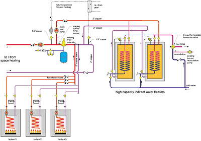
Incredible as it may seem, two additional boilers had already been set in place for future pool and hot tub heating, but neither had been piped in. Think about this: 600,000 Btu/hr. of boiler capacity is already sitting in the basement for space and DHW heating, and yet another boiler is needed to warm the pool in summer, and still another to heat the hot tub? I don't think so.
Here's a better idea. Send boilers four and five back to where they came from, and use the linked capacity of the three 200,000 boilers to handle the pool and spa via a stainless-steel heat exchanger. The revised DHW and pool heating piping is shown in Figure 6.
In the end, this system will deliver comfortable space heating and abundant DHW. The process of getting it there has taught some valuable lessons about distribution piping design and boiler capacity management. Hopefully these lessons will be applied to future systems in ways that bring out the best hydronic heating has to offer.
Good Eyes, Chuck!
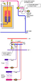
I want to thank Chuck Goodwin, PE of Bozeman, Mont., who recently contacted me about a couple of details in the figures shown in the February 2003 Hydronics Workshop column.Chuck rightly points out that the check valve on the cold water line feeding the DHW thermostatic tempering valve is incorrectly shown. The check valve must be on the recirculation line (not the cold water feed line).
He also points out that purging valves on the numerous secondary headers would make purging more efficient. I agree.
The corrected piping details are shown in the figure below.
Keep those eyes peeled as you study the details ... I'll try to do the same.
J.S.
Looking for a reprint of this article?
From high-res PDFs to custom plaques, order your copy today!


.jpg")
