Radiant Forum - November 2002
Our intent is to promote wide dissemination of ideas and technical information. Opinions expressed by either Siegenthaler or the correspondents about specific products and techniques are theirs alone, and should not be construed as a PM endorsement.
If you have a question regarding radiant heating systems, please send it to "Radiant Forum," c/o Plumbing & Mechanical, 1050 IL Route 83, Suite 200, Bensenville, IL 60106; or e-mail John at JohnSiegen@aol.com.

To Lift Or Not To Lift
Does it matter where the tubing and welded wire reinforcing (WWR) is located within the thickness of a concrete slab? Yes, it does. The thermal output of a slab-on-grade radiant panel depends on the depth of the tubing within the slab. Figure 1 shows the effect of tubing depth on heat output for a 4-inch thick, bare concrete slab operating with 100-degree F water, and resting on 1 inch of extruded polystyrene insulation.
The deeper the tubing is in the slab, the greater the upward resistance between the tubing and the floor surface. The higher resistance increases the water temperature necessary for a given rate of heat output.
Another parameter affected by tube depth is underside heat loss. The closer the tubing is to the bottom of the slab the greater these losses, both with and without underslab insulation.
Finally, when the tubing ends up near the bottom of the slab most of the slab's thermal mass is effectively above it. Since there's more thermal mass between the tubing and the floor surface, the warm-up time following a call for heat is lengthened. So is the cooling time of the slab after heat input is interrupted by system controls.
This can lead to problems in buildings with significant internal heat gains for sunlight or other sources.
Beside the thermal performance issue, welded wire reinforcing provides very little structural enhancement when positioned at the bottom of the slab.
According to published reports from the Wire Reinforcement Institute (www.wirereinforcementinstitute.org, a single layer of WWR should never be placed below mid-depth of the slab. A common recommendation is to place the WWR between one-third or one-half the depth of the slab below the top surface. For consistency, the WRI highly recommends supporting the WWR using one of several types of supports prior to placing the concrete.
Conclusion: From both a thermal and structural standpoint, the tubing and WWR should be between one-third and one-half of the slab's thickness below its upper surface. The exception to this is under sawn control joints where the tubing should be sleeved and held at the bottom of the slab.
I would like to use a buffer tank with a low mass boiler. How should it be piped into the system?
Buffer tanks add thermal mass to the system by increasing water volume. This is often helpful when a fixed firing rate (nonmodulating) boiler is connected to a distribution system with many independently controlled zones.Such configurations can cause the rate of heat generation to be much higher than the rate of heat release. Without thermal mass to temporarily "soak up" the extra heat output, the boiler will quickly reach its high limit and shut off. Such short cycling can lead to higher emissions, scale formation, lowered efficiency and premature failure of devices such as hot surface igniters.
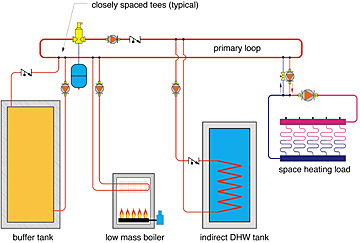
I have found that piping the buffer tank as a secondary circuit in a primary secondary system works well. This concept (shown in Figure 2) allows the possibility of the buffer tank being either "online" or "offline" with the primary loop, depending on the operating mode of the system.
For example, during domestic water heating there is little point in passing heated water through the buffer tank. The thermal mass of the indirect tank provides the necessary buffering.
In such a case, the control wiring should prevent the secondary circulator for the buffer tank from operating. This piping arrangement is also conducive to future control systems that may be sophisticated enough to know exactly when the buffer tank should be used. Then it's simple a matter of turning the secondary circulator on and off to include or exclude the thermal mass of the tank.

Does boiler bypass piping protect a conventional boiler used in a low temperature radiant system?
Not under all conditions. In a situation where boiler heat output equals or slightly exceeds the rate of heat release, bypass piping can maintain a conventional boiler above dewpoint.However, most hydronic heating systems experience quite a bit of transient operation in which the rate of heat release by the distribution system is greater than the rate of heat generation by the boiler. This is especially true of low temperature/high mass heated slabs.
Whenever and however this occurs, the first law of thermodynamics mandates that the system water temperature must drop. This includes the temperature in the boiler. Bypass piping does not allow the boiler to exempt itself from this situation.
In situations where a boiler supplies a very steady low temperature load that seldom if ever exceeds the output of the boiler, a bypass arrangement can raise the temperature rise across the boiler high enough to prevent flue gas condensation.
However, such loads are the exception rather than the norm. The conservative approach is to install a mixing assembly between the boiler and distribution system with the intelligence to restrict hot water flow into the mix when the boiler temperature is low enough to allow flue gas condensation.
Nearly all types of electronic mixing controllers have this capability. It can also be achieved by installing a second thermostatic mixing valve as shown in Figure 3.
An aquastat that turns the boiler pump off when the boiler temperature drops is a crude approach to the problem. Because of the on/off rather than modulating control action, this approach creates frequent and wide swings in boiler return temperature that thermally stresses the heat exchanger.
It's like driving your truck along by repeatedly popping the clutch. You can do it, but I certainly don't have to tell you there is a smoother control technique available.
Is a circulator needed on the boiler side of a four-way motorized mixing valve?
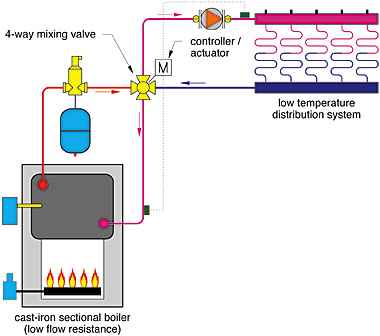
It depends. Countless four-way mixing valves have been used very successfully in systems without boiler-side circulators (primarily in Europe). Many European boiler companies sell pump/mixing valve assemblies designed to attach to the boiler without need of a separate boiler-side circulator.
There are several factors that make this possible. The first is low flow resistance through the boiler loop. This is usually the case when the four-way valve is located relatively close to a cast-iron section boiler. Flow through the boiler is caused by the slight pressure drop across the four-way valve from the system return port to the system supply port (see Figure 4).

Another factor is the relatively low flow rate of boiler water needed in the mixing process. The ratio of the boiler loop flow to the distribution loop flow can be calculated using Formula 1:
Flow Ratio = fboilerloop ? fdistribution loop = Tds - Tdr ? Tboiler - Tdr
Where:
Tds = supply temperature to distribution loop (degrees Fahrenheit)
Tdr = return temperature of distribution loop (degrees Fahrenheit)
Tboiler = supply temperature of boiler (degrees Fahrenheit)
For example: Assume a boiler supplies 180-degree F water to the mixing valve at design load conditions. Under these same conditions the mixed water temperature supplied to the distribution system is 110 degrees F, and the water returned from the distribution system is 90 degrees F. The flow rate in the distribution system is 10 gpm. The flow ratio is:
flow ratio = fboilerloop ? fdistribution loop = (110-90) ? (180-90) = 0.22
The flow rate through the boiler is then 0.22 x 10 = 2.2 gpm. It doesn't take a whole lot of pressure differential to push such a low flow rate through a low resistance cast-iron boiler and a few feet of generously sized piping. It's also worth noting that cast-iron sectional boilers are generally not "flow sensitive" and thus can operate with a trickle of flow if that is all the system needs.
One could even argue that the "gravity" flow effect present in such a boiler loop helps induce some flow through the boiler.
Obviously not all systems present such operating conditions. Some low-mass boilers must operate at minimum flow rates. Some boiler loops may have high flow resistance due to the boiler's heat exchanger, or when the mixing valve is located far from the boiler.
In such situations, a separate boiler loop pump should be installed as shown in Figure 5. The hot side of the mixing valve is connected to the boiler loop using closely spaced tees (e.g., as a secondary circuit). This arrangement restores the low resistance path on the hot side of the four-way mixing valve. It also prevents interference between the boiler loop circulator and the distribution circulator.
Looking for a reprint of this article?
From high-res PDFs to custom plaques, order your copy today!


