Minitube Mods
John Siegenthaler, P.E.
If you've been following the Hydronics Workshop column for a few years, you may remember reading about minitube systems. In the April 1997 column I described this variation on the basic concept of variable speed injection mixing. A complete description was also presented in the August 1999 issue of PM Engineer (check it out at www.PMEngineer.com).
A schematic of a typical minitube system is shown in Figure 1.
For example, when the temperature drop between the supply and return side of a distribution system is 80 degrees F, each gallon/minute of flow carries about 40,000 Btu/hr to the load. That's four times more heat than is carried with a delta T of 20 degrees F. Do the math and you'll find that 1/2-, 5/8- or 3/4-inch tubing can carry a substantial amount of heat and save you a substantial amount of money.
The minitubes not only carry water to and from the radiant manifolds, they also provide the head loss needed to allow the injection pump to operate over a wide speed range. The latter is desirable for accurate temperature control.
Since the minitube concept was first published, many contractors have learned how to apply it. Some even came up with improvements, spin-offs or novel applications they've described to or shown me. This month I want to pass some of these along as examples of what creative hydronic thinking can accomplish.
Old Pipes/New Brains
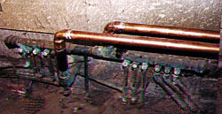
Although most minitube systems are installed in new construction, the concept certainly holds potential for retrofit jobs. John Pughe of Utica, N.Y., recognized this. After learning how a minitube system works, he used it to supply a remote portion of an older copper-tube floor heating system.Figure 2 shows the new piping connected to an old manifold that's located quite a distance from the new boiler. Rather than do the mixing near the boiler, and run 1.25-inch rigid copper tubing all the way to the manifold, John decided to use 5/8-inch PEX-AL-PEX minitubes and do the mixing at the manifold.
Figure 3 is a photo John sent me showing supply and return temperatures with the system in action. The left gauge is on the supply minitube, and reads 185 degrees F. The right gauge shows the return temperature at 95 degrees F. That 90-degree temperature difference lets every gpm of injection flow carry about 44,000 Btu/hr. to those remote floor circuits.
The system's in and operating well. Imagine what the original installers would think of the modern technology that's keeping the tubing they laid down more than 50 years ago delivering comfort to the home's current occupants. Who says you can't teach an old dog new tricks? (No, not you John; I'm talking about that old heating system.)

Way Up North
Another adaptation of the minitube concept comes from Roy Collver of Mechanical Systems 2000 in Calgary, Alberta. Roy was the first person I bounced the minitube concept off after sketching it back in 1996. At the time I wasn't totally convinced it would work. I expected Roy, a real diehard pipes-and-pumps type of guy, to show me what I was overlooking.A few days later Roy calls to say he's going to change the current design for the floor heating system in a 70,000-sq./ft. industrial building to make it into a minitube system. Gulp.
Oh and by the way, the building was in Fort McMurray, Alberta. In case you've never been there it's about a 10-hour drive north of Calgary, and has a winter design temperature of - 41 degrees F. What a great place to try out an unproven heating concept, don't you think?
Anyway, Roy went over all the numbers and was confidently ready to serve as the official guinea pig for the minitube system. His variation on the original concept was to use on/off injection pumping rather than variable speed injection pumping. (We discussed this concept in the June 2001 Hydronics Workshop column.)
The injection pump cycles on and off to maintain a calculated "average" supply temperature to the distribution system. It's well suited to slab heating because the high thermal mass dampens out the pulses of heat input to produce a relatively stable floor surface temperature.
At the time of the installation Roy estimated the savings in piping was about $11,000 relative to the conventional distribution system originally planned. The system is up and running as expected, and Roy is busy looking for more good minitube applications.
Hydronics In Harvard
Still another twist on the minitube concept comes from Piotr Zelasko of Park Supply in Chicago. When faced with designing a hydronic floor heating system for an apartment building in Harvard, Ill., Piotr remembered the "magic" that's possible with a high-temperature drop system. He designed a system that carried hot water through a parallel primary loop to "satellite" manifold loops in each apartment as shown in Figure 5. The largest pipe used outside the mechanical room is 1-inch PEX-AL-PEX.Piotr used a boiler reset control to reduce the supply temperature. The manually set mixing valves in the manifold loops allow proportional reset of the supply temperature to the floor circuits. This is all done without additional mixing controls. The system is simple, reliable and affordable.
Incidentally, Piotr and Co. won an RPA System Showcase award with this project. You can read more about it the 2001 Radiant Heat Report, and the July 2001 Hydronics Workshop column, both at www.PMmag.com.

A Bulge In The Pipe
Another concept came from discussing the minitube system with Tibor Kovacs of the IPEX Corp. in Toronto. After looking at the "classic" parellel primary loop piping shown in Figure 1, he raised an interesting question: Why can't the individual minitube take-offs be set up as shown in Figure 6?
The idea had merit provided the pressure drop in the common piping could be kept to a minimum. Being one who'd rather sketch piping schematics than read Vanity Fair, I kept doodling away at the concept. I ended up with the arrangement shown in Figure 7.
Since all the takeoffs are at the same location along the piping loop they should all be at the same pressure and water temperature. The pressure drop between an upstream takeoff and its associated downstream return should be extremely small, perhaps even less than between closely spaced tees.
Like I told Roy, it's only a sketch, but I do think it would work. It could even be used for other primary/secondary applications where several secondary circuits all need to be supplied with the same water temperature. Perhaps some enterprising hydronician or manufacturer would like to give it a try.
If you've used a minitube distribution system, or some variant of it, I'd like to hear from you. Drop me an e-mail and tell me about your application. Who knows, one day your work might be prominently displayed in the Museum of Minitube Science.
Links
Looking for a reprint of this article?
From high-res PDFs to custom plaques, order your copy today!


