Questionable Conduct
John Siegenthaler
For as long as I have been involved with hydronics I've heard "discussions" on how the type of tube used in a heated slab affects performance.
One camp usually points out that the thermal conductivity of copper tubing is more than a thousand times greater than that of PEX. To the thermally uninitiated this might suggest that using copper tubing in a radiant floor slab will yield one thousand times more heat output. I'm sure many of you can picture Joe Homeowner in wide-eyed amazement when such a statistic is tossed out during a sales presentation.
Another camp may promote the idea that the tubing material has virtually no effect on the thermal performance of the floor. At the risk of sounding Clintonian, the validity of this statement depends on the meaning of "virtually no."
Intuitively, anyone who understands the concept of thermal conductivity expects that tubing with higher thermal conductivity will provide better heat flow from the water to the slab. But how much of a difference is there between, say copper, PEX and EPDM tubing? Is the difference in performance worth the price or installation requirements of one tube over another?
Simulation Vs. Speculation
You may recall the October 2001 Hydronics Workshop in which the issue of tubing size vs. thermal performance was analyzed. A finite element heat transfer model was used to simulate the performance of several tube sizes. The conclusion: Tube size does have a slight impact on thermal performance, with larger diameters offering slightly better rates of heat transfer when all other operating conditions are equal.This same modeling technique can be used to estimate the relative performance of different tube materials. The results should shed some quantitative information on what has been mostly a qualitative debate.
So on a dark, cold day last December, I pulled out spec sheets for several types of commercially available tubing and began the modeling process. Figure 1 lists the physical data used for the tubing options.
Several finite element models in which the tube was centered (vertically) in a 4-inch concrete slab at 12-inch spacing were constructed. Each model assumed the slab was covered with 3/8-inch oak flooring, and had 1 inch extruded polystyrene underside insulation. The soil temperature under the insulation was set at 65 degrees F.
Each finite element model consists of hundreds of interconnected points called "nodes" that are distributed throughout the materials making up floor assembly. In a feat that anyone who has suffered through matrix algebra can appreciate, the simulation determines the temperature at each node.
The number crunching power needed to do this cost millions of dollars when first used to develop aircraft in the 1960s. Now it can be run on an average PC and used to study subjects like heat transfer in floor slabs.

The section of floor shown in Figure 2 starts 6 inches to the left of the tube's center, and extends to 6 inches right of the tube's center. Assuming there is another tube at the same operating temperature 12 inches to the left and right of this tube, the heat transfer across the left and right edge of the section would be zero. Thus, one could imagine two or three of these sections connected side by side as shown in Figure 3.
The surface temperature profile predicted by the simulation using EPDM tubing with 120-degree F water is shown above the floor construction. As expected the floor is warmest directly above the tubing and coolest half way between adjacent tubes. In this case, the peak to valley variation is about 13.3 degrees F.

Practical Performance
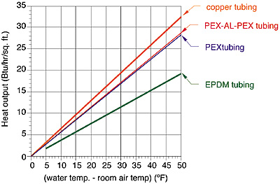
A simulation was run for each tube type using water temperatures of 80, 100 and 120 degrees F. Surface temperature data was collected for each run and used to estimate the total heat output from the upper surface of the floor. The results are shown in Figure 4.The graph shows the predicted heat output of the floor (in Btu/hr./sq. ft.) vs. the difference between the average water temperature in the tube and the room air temperature.
For example: If the average water temperature was 108 degrees F, and the room air temperature was 68 degrees F, the difference would be 108 - 68 = 40 degrees F.
Locating 40 degrees F on the horizontal axis and reading up to the line for copper tube, then over to the vertical axis gives a predicted heat output of about 26 Btu/hr./sq. ft. The same assembly using a 1/2-inch PEX tube would be expected to release about 22.5 Btu/hr./ sq. ft.
The results confirm expectations that higher tube conductivity yields greater heat output. However, the copper tube with a thermal conductivity more than a thousand times greater than that of PEX tubing certainly yields no where near a thousand times the heat output. Based on numbers from Figure 4, using copper vs. PEX tubing would yield about 14.5 percent more heat output under the same operating conditions.
Another practical way to look at these numbers is to determine the required water temperature for a given level of heat output. In the case of copper vs. PEX, the latter requires a water temperature about 5.5 degrees F higher to produce an output of 25 Btu/hr./sq. ft. The increase in temperature would be proportionally higher for higher heat outputs and vice versa.
The difference between PEX and PEX-AL-PEX is scant. I used very narrow lines for PEX and PEX-AL-PEX tubing in Figure 4 so you can see that these tubes have virtually identical thermal performance.
The relative performance difference between PEX and EPDM tubing is more significant. Based on these simulations, PEX would yield about 47 percent higher heat output than the EPDM tubing at the same operating temperatures. This is due to differences in thermal conductivity of the tube wall, as well as differences in wall thickness.
The EPDM tubing has a thicker wall and thus offers more resistance to heat flow. In terms of water temperature, the EPDM tubing requires water approximately 21 degrees F higher than that of PEX tubing to produce the same 25 Btu/hr./sq. ft. heat output for the floor construction being simulated.
So What's The Point?
A heated floor is a sandwich of several materials. Heat flow through such an assembly depends on all the thermal properties of all these materials. Using a high conductivity tube alone does not make a tremendous difference in thermal performance because other materials can "bottleneck" the process. Differences in floor-covering resistance, for example, could easily have more of an effect on performance than does the conductivity of the tube wall.The lower the thermal conductivity of the tubing the higher the required operating water temperatures for a given rate of heat output. Higher water temperatures are possible from many of the hydronic heat sources currently used, boilers in particular.
Keep in mind, however, that the efficiency of condensing boilers and geothermal heat pumps decrease significantly at higher operating temperatures. Any installation detail that allows an incremental drop in the required supply water temperature will enhance the performance of these heat sources. Such detailing may include the type of tubing used as well as tube spacing, underside insulation and floor covering.
The usual caveat about the limitations of computer simulation is in order. First, this simulation is for a tubing of given sizes, installed at 12-inch centers in a 4-inch thick concrete slab, with specific finish floor and underside insulation. Changing any of these parameters will have some effect on the relative performance. Still, all other parameters being equal, tubing with higher thermal conductivity will always yield incrementally better performance.
This comparison was not put together to favor any one material vs. another. All the tubing options modeled have demonstrated their ability to perform in radiant floor heating applications. Instead, the comparison shows that citing large differences in a specific physical property does not necessarily translate into huge differences in performance. As with so many other things hydronic -- it's the system, and not just a single component that counts.
Looking for a reprint of this article?
From high-res PDFs to custom plaques, order your copy today!


