Determining Flow Rates in Parallel Piping Systems Constructed of Smooth Tubing

Editor's Note: Some of the formulas referenced in this article could not be reproduced online. Please see print edition for these formulas.
Over the years, I've noticed an innate tendency in people just learning about hydronic heating. When given a group of piping components such as valves, multiple heat emitters, pumps and so on, most folks want to connect them together in a series circuit. I suppose that's natural, considering they understand that water going out into the distribution system also has to come back.
While it's true that series loop systems have their place in hydronic heating, it's also true that place is rather small. Issues of temperature drop from one heat emitter to the next, the inability to zone separate heat emitters, and the potential for high head loss combine to limit series circuits to relatively small, single zone applications.
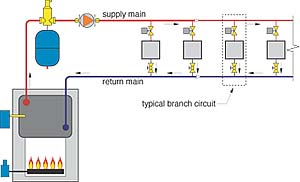
Parallel distribution piping systems, as shown in Figure 1, overcome many of the limitations of simple series circuits. They allow each heat emitter to operate with essentially the same inlet water temperature. They also allow the flow through each heat emitter to be adjusted or turned off while flow continues through other branches.
Questions often arise as to how to analyze the flow rates and head losses in parallel distribution systems. Unlike series circuits, in which the flow rate is the same through all components and head losses can simply be added up, the analysis of parallel systems requires a bit more mathematical sophistication.
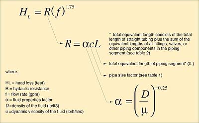
Figure 2
An Electrical Analogy
I prefer to think of piping circuits as analogous to electrical circuits. Every tube, fitting, valve, heat emitter and other piping component in the system can be thought of as having a "hydraulic resistance." The relationship between the hydraulic resistance, flow rate and associated head loss in a system using smooth tubing, is given in Formula 1.
HL = R(f)1.75
Where:
HL = head loss across a piping device due to viscous friction (feet of head)
R = hydraulic resistance of the piping device
f = flow rate of fluid through the piping device (gpm)
1.75 = exponent of f
Formula 1 is derived from the widely used Darcy-Weisbach equation. It incorporates an empirical relationship for the Moody friction factor based on turbulent flow in smooth tubing (e.g. copper, PEX, and PEX-AL-PEX). It is valid for flows with Reynold's numbers of 4,000 to approximately 200,000. This covers most of the operating conditions found in residential and light commercial hydronic systems.
The hydraulic resistance can be calculated using the formulas given in Figure 2, along with the supporting data given in Tables 1 and 2.
Table 1. Value of pipe size factor (C) for several types of smooth tubing
Tube (size & type) C value 3/8" type M copper 1.016
1/2" type M copper 0.3335
3/4" type M copper 0.06196
1" type M copper 0.01776
1.25" type M copper 0.006808
1.5" type M copper 0.0030668
2" type M copper 0.00083317
2.5" type M copper 0.0002977
3" type M copper 0.0001278
3/8" PEX (I.D. =0.36") 2.9336
1/2" PEX (I.D. = 0.475") 0.7862
5/8" PEX (I.D. = 0.584") 0.2947
3/4" PEX (I.D. = 0.670") 0.1535
1" PEX (I.D. = 0.86") 0.04688
3/8" PEX-AL-PEX (I.D. = 0.35") 3.354
1/2" PEX-AL-PEX (I.D. = 0.47") 0.8267
5/8" PEX-AL-PEX (I.D. = 0.63") 0.2056
3/4" PEX-AL-PEX (I.D. = 0.79") 0.07016
1" PEX-AL-PEX (I.D. = 0.98") 0.0252
Table 2. Equivalent Lengths of Fittings and Valves
Copper Tube Size Fitting or Valve(1)
1/2"
3/4"
1"
1.25"
1.5"
2"
90-degree elbow
1.0
2.0
2.5
3.0
4.0
5.5
45-degree elbow
0.5
0.75
1.0
1.2
1.5
2.0
Tee (straight run)
0.3
0.4
0.45
0.6
0.8
1.0
Tee (side port)
3.0
4.5
5.5
7.0
9.0
Reducer coupling
0.4
0.5
0.6
0.8
1.0
1.3
Gate valve
0.2
0.25
0.3
0.4
0.5
0.7
Globe valve
15.0
20
25
36
46
56
Angle valve
3.1
4.7
5.3
7.8
9.4
12.5
Ball valve(2)
1.9
2.2
4.3
7.0
6.6
14
Swing check valve
2.0
3.0
4.5
5.5
6.5
9.0
Butterfly valve
1.1
2.0
2.7
2.0
2.7
4.5
Footnotes:
- Data for soldered fittings and valves. For threaded fittings or valves, double the listed value.
- Based on a standard port ball valve. Full port valves would have lower equivalent lengths.
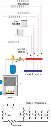
Figure 3
When There's More Than One Way to Go
Figure 3 shows an example of a distribution system containing several parallel branches, as well as "common" piping through which all system flow passes. In this system, the parallel branches begin at a short manifold and end at a second short manifold. The resistance of the manifold segment between the beginning points of each branch is considered negligible. The same holds true for the manifold segment between the ending points of each branch.
Below the piping schematic is a hydraulic resistance diagram of the system. The five parallel resistors each represent the total hydraulic resistance of one of the parallel circuits. Each would include the resistance of the tubing, fittings, valves and heat emitter(s) in that branch circuit. Another resistor symbol represents the total hydraulic resistance of the common piping, which is in series with the group of parallel resistors. The other resistor symbol represents the hydraulic resistance of the boiler.
The total flow through the common piping divides among the parallel branches and eventually recombines at a common return point. The percentage of total flow passing through each branch depends on the hydraulic resistance of that branch relative to the others.
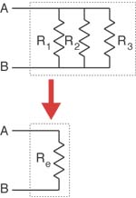
Figure 4
When the hydraulic resistance of all parallel piping strings in a given piping assembly is known, they can be combined into a single "equivalent resistance." This concept is shown in Figure 4.
The value of the equivalent resistance of any number of parallel branches can be calculated using Formula 3.
Re = [(1/ R1)0.5714 + (1/ R2)0.5714 + (1/ R3)0.5714 + . . . + (1/ Rn)0.5714]-1.75
Where:
Re = the equivalent hydraulic resistance of all parallel piping strings
R1 = the hydraulic resistance of branch piping path 1
R2 = the hydraulic resistance of branch piping path 2
R3 = the hydraulic resistance of branch piping path 3
Rn = the hydraulic resistance of the last branch piping path
The equivalent resistance is a single resistance connected between the common beginning and ending points of the parallel branches. This single resistance represents the combined effect of all original parallel hydraulic resistances. Mathematically, the equivalent resistance will always be less than the smallest of the parallel branch resistances.
Once the equivalent hydraulic resistance of the parallel branches is found, it can be added to the hydraulic resistance of the common piping. This is possible because the equivalent resistance of the parallel branches and the resistance of the common piping are in series with each other. The overall piping system can thus be reduced to a single total resistance. By entering the value of this resistance into Formula 1, it is possible to generate the system curve of the overall system. Pump curves of candidate circulators can then be overlaid on this system curve to determine the operating point, and hence the flow rates through the circulator and common piping.
Once a circulator is selected, and the total flow in the common piping is determined, the flow rates in the individual branches are found using Formula 4.
fi = ftotal( Re/Ri)0.5714
Where:
fi = flow rate through parallel path i (gpm)
ftotal = total flow rate entering the common point of the parallel paths (gpm)
Re = equivalent hydraulic resistance of all the parallel branches
Ri = hydraulic resistance of parallel piping path i
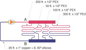
Figure 5
Here's an Example
Use the methods presented to find the equivalent resistance of the piping system shown in Figure 5. All four parallel paths are 1/2-inch PEX tubing, and the average water temperature in the system is 100 degrees F. Also assume the common piping path consists of 20 feet of 1" copper with eight 90-degree elbows. Reduce the system to a single total hydraulic resistance and plot the system curve. Next, determine the system flow rate based on the pump curve shown. Finally, determine the flow rate in each branch circuit.
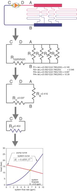
Figure 6
The hydraulic resistance diagram for the overall system is shown near the top of Figure 6. The diagrams below it show the sequence through which the original diagram is reduced to a single total resistance.
To get the values of the resistance, one uses the data and formulas given in Figure 2. The density of 100 degrees F water is 61.97 lb/ft3. The dynamic viscosity of 100 degrees F water is 0.0004573 lb/ft/sec. From these the value of (a) can be calculated:
(a) = (D/u)-0.25 = (61.97/0.0004573)-0.25 = 0.05212
The values of the fours parallel resistances are as follows:
200-ft. piping path: R1 = acL1 = (0.05212)(0.786)(200) = 8.193
50-ft. piping path: R2 = acL2 = (0.05212)(0.786)(50) = 2.048
100-ft. piping path: R3 = acL3 = (0.05212)(0.786)(100) = 4.097
300-ft. piping path: R4 = acL4 = (0.05212)(0.786)(300) = 12.29
The equivalent resistance of the four parallel resistances is found by plugging these resistance values into Formula 3 and calculating:
Re = [(1/8.193)0.5714 + (1/2.048) 0.5714 + (1/4.097)0.5714 + (1/12.29)0.5714]-1.75 = 0.416
The total equivalent length of the common piping is:
20 + 8(2.5) = 40 feet
The value of the common resistance is:
R5 = acLc = (0.05212)(0.01776)(40) = 0.037
The total resistance is found by adding the equivalent resistance of the parallel circuits to the resistance of the common piping:
Rt = 0.416 + 0.037 = 0.453
The system curve is now plotted using Formula 1.
The intersection of the system curve with the pump curve gives the operating point. In this case, the operating flow rate is approximately 6.5 gpm.
The individual branch flows can now be found using Formula 4, once for each branch:
(see print edition)
A final check is to add the branch flow rates to ensure the total matches the total system flow:
1.2 + 2.6 + 1.76 + 0.94 = 6.5 (check)
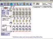
Figure 7
It Can Get More Complicated
In the previous example, there was no hydraulic resistance between the individual branch circuits. Although this is a reasonable assumption for a typical radiant heating manifold, it would not be true for a typical two-pipe distribution system. An accurate model would have to account for the hydraulic resistance of each parallel branch as well as the resistance of each segment of main piping between the branches. This can be done through repeated series and parallel resistance combinations. Such a process is extremely tedious and error-prone if done manually.
It quickly becomes apparent that such calculations need automation to be useful as a routine design tool. One approach would be to implement the formulas and data as a spreadsheet. Another would be to write a dedicated software package in which a resistance network is automatically constructed as parallel branches and interconnection piping are specified. Once fully specified, the resistance network is reduced to a single equivalent resistance, with branch flow determined through the methods described above. An example of one program that does this, (the Hydronic Circuit Simulator), is shown in Figure 7. The Hydronic Circuit Simulator is one of several design tools available in the Hydronics Design Studio software package, available at www.hydronicpros.com.
Summary
The analysis of parallel piping systems is more mathematically complex than that required for series circuits. The method presented in this article can be used for such analysis in systems containing smooth tubing. When implemented in software, this approach allows rapid determination of flow rates in many types of hydronic distribution systems containing parallel branches.
Looking for a reprint of this article?
From high-res PDFs to custom plaques, order your copy today!


