Different ways to pipe a thermal storage tank
Four-pipe vs. two-pipe.


Figure 1.

Figure 2.

Figure 3.
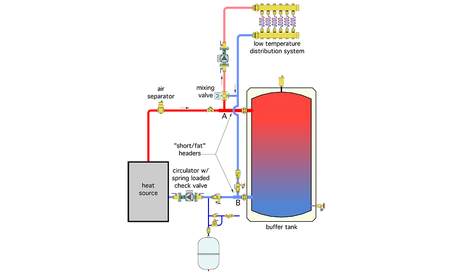
Figure 4.
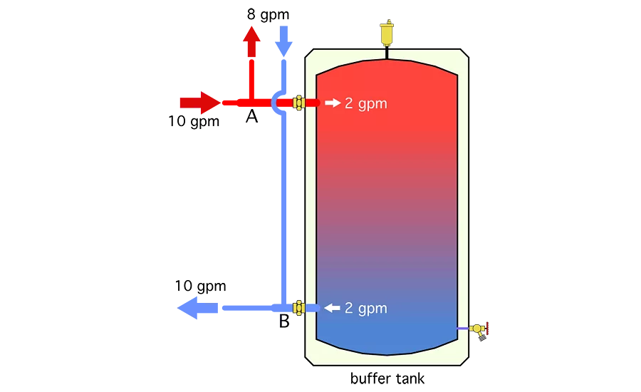
Figure 5.
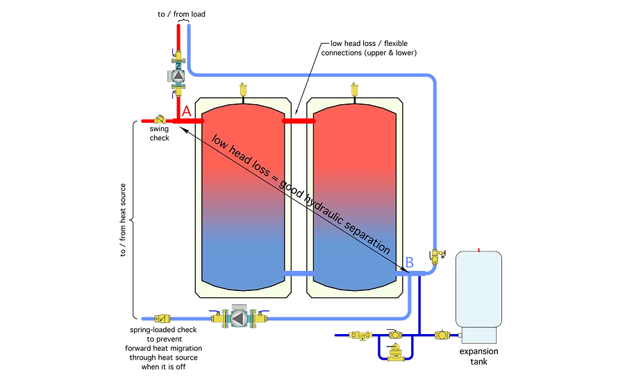
Figure 6.
Most hydronic-based renewable energy heat sources require a thermal storage tank.
Examples include systems using solar thermal collectors, biomass boilers and in some cases applications using heat pumps. The latter is common when a geothermal heat pump or air-to-water heat pump with a fixed-speed compressor is combined with a zoned hydronic distribution system.
In North America, one of the most common arrangements for a thermal storage tank is to install the unit between the heat source and distribution system as shown in Figure 1.
Water from the heat source enters the tank’s upper-left side wall connection. Water headed for the distribution system exits from the upper-right side wall connection.
If the entering water is hotter than the water in the upper portion of the tank, it is slightly less dense and will remain near the top of the tank. Still, there will be some mixing between the entering hot water and the water in the tank. If the water in the tank is about the same temperature as the entering water, this interaction will have minimal effect on the water temperature leaving the upper tank connection.
However, if the water in the upper portion of the tank is significantly cooler than the entering water, this mixing will reduce the supply temperature to the distribution system relative to that of the entering water. This would be most noticeable after the tank was allowed to cool for several hours, followed by simultaneous heat input and load operation.
A swing check valve is installed on the pipe leading into the thermal storage tank from the heat source. It is there to stop reverse thermosiphoning when the tank contains heated water, but the heat source is not operating. Without it, it is likely that hot water from the tank would set up a slow but persistent reverse flow through the heat source, which would act as a heat sink and thus accelerate the rate of standby heat loss from the tank.
The upper-right connection leading to the distribution system also contains a check valve. Here I suggest a spring-loaded check valve to stop forward thermosiphoning when the distribution system is not operating. A swing check does not have sufficient forward-opening resistance to prevent forward thermosiphoning. Most spring-loaded check valves have a forward-opening pressure requirement of about 0.5 psi, which generally is enough to stop this unwanted flow.
Cooler water returning from the distribution system tends to remain in the lower portion of the tank and migrate across to the lower-left sidewall connection back to the heat source. This minimizes interaction with hot water at the top of the tank and helps maintain desirable temperature stratification.
If the flow rate from the heat source is lower than flow to the distribution system, cooler water will migrate upward within the tank. Under this condition the tank is giving up heat to the load. If the flow rate from the heat source is greater than the flow rate to the distribution system, hot water migrates downward within the tank. The average tank temperature increases as the excess output from the heat source is stored. Both conditions are shown in Figure 2.
Ancillary benefits
A thermal storage tank piped as shown in Figure 1 also provides excellent hydraulic separation between the heat source circuit and load circuit. This happens because the internal flow velocities within the tank are extremely low compared to the flow velocities in the piping connected to the tank. There almost is zero head loss across the tank or from top to bottom.
The heat stored in the tank also can be used for domestic water heating or preheating. This can be done using an internal coil heat exchanger or with the “on-demand” assembly shown in Figure 3.
When there is a draw of hot water, a flow switch within the tankless electric water heater closes. This switch closure is used to turn on a small circulator that moves hot water from the upper portion of the tank through the primary side of a stainless-steel brazed-plate heat exchanger and then back into the lower portion of the tank.
Cold domestic water passes through the other side of this heat exchanger and absorbs heat. The temperature of the heated domestic water leaving the heat exchanger obviously depends on the temperature of the storage tank. With a reasonably sized heat exchanger, the departing domestic water temperature can generally be within 5º F of the temperature at the top of the storage tank. The thermostatically controlled electrical tankless heater simply “tops off” the domestic water temperature as needed. A thermostatic mixing valve provides anti-scald protection before the domestic hot water passes into the plumbing distribution system.
Rethinking tank piping
The piping shown in Figures 1, 2 and 3 all involve four principal piping connections on the sides of the thermal storage tank, two into the upper portion and two into the lower portion. Although these principal connections can function well, they are not the only way to connect a thermal storage tank into the system.
After looking over many schematics from European sources, especially those involving biomass boilers, I have noticed a trend that places the thermal storage tank in a different arrangement relative to the heat source and load. This alternate arrangement is shown in Figure 4.
In this configuration, flow from the heat source does not pass through the tank on its way to the distribution system. Instead, the distribution system extracts flow from the piping between the tank and heat source. Any hot water that flows from the heat source that is not pulled off into the distribution system, passes into the tank as shown in Figure 5.
In this “two-pipe” tank scenario, the flow velocity entering the tank is lower than the “four-pipe” arrangement shown in Figures 1 through 3. Lower entering flow velocities help to preserve temperature stratification and thus maintain the warmest water at the top of the tank, ready for transfer to the load.
If the heat source is off, stored hot water from the tank flows backward from the tank and into the distribution system at Point A. It also is possible for some flow to enter the distribution system from the heat source while the remainder of the required flow comes from the tank. This happens when the distribution system requires more flow than currently is passing through the heat source.
Another benefit of the two-pipe tank configuration is the distribution system has access to the hottest water in the system before that water passes through the upper portion of the tank. This would be an advantage if the tank has cooled for several hours before the next call of heat occurs.
A four-pipe tank under such a condition would cause the incoming heated water to mix with the cooler water. This would reduce the water temperature supplied to the load until the upper portion of the tank has warmed back to normal operating conditions. This effect would be especially noticeable when the system is first started and the water in the tank is at room temperature.
The two-pipe configuration shown in Figure 4 also eliminates two of the principal sidewall connections on the tank. One could view this as a benefit because it might reduce the cost of the tank, all other specifications being the same. However, I contend it is better to work with tanks that have more connections than those absolutely necessary for a given application. The extra connections always can be plugged off if not needed. Or they can be used to attach devices such as sensor wells, thermometers, sight-gauge connections or piping connections that better match incoming flows to the likely temperature stratification of the tank. Extra connections also might be used to accommodate the on-demand DHW assembly shown in Figure 3.
Keep it close
The degree of hydraulic separation between the distribution circulator and heat-source circulator provided by the two-pipe configuration depends on the length and size of piping between the tees where the distribution subsystem connects and the connections to the tank. This piping should be short and generously sized to minimize head loss – thus the callout for “short/fat” headers in Figure 4.
If tanks with the four principal piping connections shown in Figures 1 through 3 are available, they can be joined together in a “close-coupled” arrangement as shown in Figure 6.
This piping allows the two tanks to maintain flow dynamics very similar to the single two-pipe tank shown in Figures 4 and 5. To maintain good hydraulic separation across the tank array, the couplings between the tanks should create minimal head loss. A short flexible connector works well and compensates for any slight misalignments of the tank connections due to manufacturing tolerances or a less than perfectly flat floor slab under the tanks.
Either the traditional thermal storage tank piping shown in Figures 1 through 3 or the alternate method shown in Figures 4, 5 and 6 can work. Both have been used on successful installations.
It is likely to come down to what tanks are available, how the piping connections on the tank are sized and located, and how those tanks would be optimally located in relationship to the other components and subsystems.
This article was originally titled “Four-pipe vs. two-pipe” in the March 2016 print edition of PM Engineer.
Looking for a reprint of this article?
From high-res PDFs to custom plaques, order your copy today!