Hydronics Workshop | John Siegenthaler
There are still viable applications for solar thermal technology
Sōl Survivor

Image courtesy of chinaface / iStock / Getty Images Plus
These days, the term “solar energy” is almost always associated with photovoltaic (PV) systems that produce electricity from sunlight. Those systems range from a single small PV module used to maintain charge in a 12-volt battery, to acre upon acre of land covered with thousands of PV modules to create a “solar farm” that, by day, generates megawatts of power. Where I live in upstate New York, the latter are sprouting up in many local communities. Utility-scale solar developers are leveraging significant investment incentives provided by state and federal governments on their quest to reach 100% renewably-sourced electricity in the not-too-distant future. Landowners, who once made an “adequate” living from their acreage as dairy farmers, are comfortably retiring on leasing agreements made with these developers.
Few would have envisioned such a situation back in the 1970s. That’s when I got my first job with a company that designed and manufactured solar thermal collectors. Back then, solar photovoltaics was mostly reserved for remote mission critical or spacecraft applications, where the nominal $1,000/ watt cost (in 1970s dollars) was acceptable. Outside of this small niche, solar thermal applications were the norm, with much of the market focused on residential solar space heating. Houses were constructed as supporting structures for massive solar collector arrays in an attempt to approach 100% solar heating. One example, from 1978, is shown in Figure 1.
Figure 1
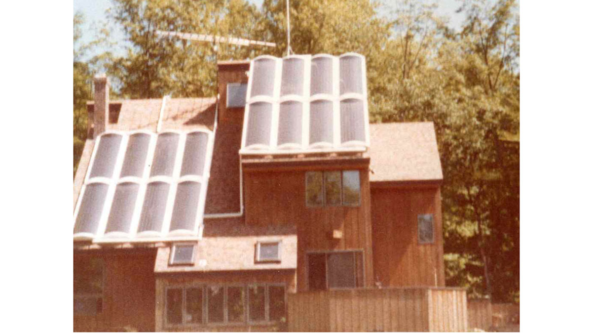
Many collector arrays of that vintage were grossly oversized for swing season loads, and required costly heat dump provisions to “survive” intense summer sunshine. A controller failure or power outage during a bright and hot summer afternoon lead to pressure relief valve openings, thermal breakdown of antifreeze solutions and even irreversible material outgassing within the collectors that degraded their subsequent performance.
That first round of interest in active solar thermal technology within the U.S. all but died during the latter 1980s, and remained in that state through much of the 1990s and first part of the 21st century. The solar coals were rekindled around 2008, driven by increasing concerns over global warming and well as some energy price spikes. However, this time around, much of the industry recognized that using solar collectors to offset a high percentage of conventional fuel for space heating was not a realistic goal in most locations, especially the Northeastern U.S.
Domestic water heating became the preferred load to be paired with solar thermal collectors. The primary rationale being that domestic water heating was a year-round load. As such, it benefited from abundant solar radiation and higher ambient temperatures for several months every year. Another benefit was that domestic water heating operated as lower average water temperatures compared to those typically needed for space heating applications.
Sweet spot
Although the market for solar thermal systems is a tiny fraction of what it once was, I still believe there are viable applications that could help in decarbonizing thermal energy systems.
One system configuration that has always interested me is what I call a “solar DHW+” system. The primary load for these systems is domestic water heating. The “+” implies a small contribution to space heating, mostly during swing seasons.
This approach keeps the collector array limited to minimize overheating potential in summer. It also leverages major components of the system, such as the thermal storage tank, for multiple functions. The energy collection potential of a Solar DHW + system is also better matched with the load in modern energy-efficient homes.
One approach to a solar DHW+ system that uses a dual coil thermal storage tank, is shown in Figure 2.
Figure 2
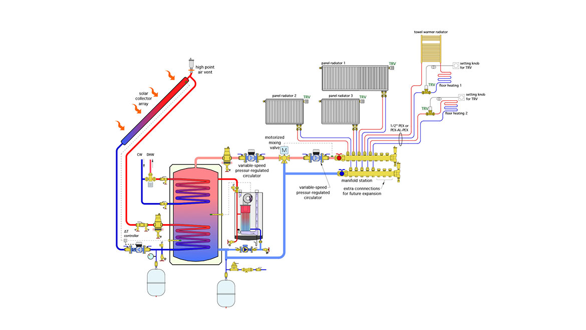
The water in the tank’s shell is “system water,” not domestic water. The lower coil provides heat input from the solar collectors. Its position within the tank maximizes the average temperature difference between the outer surface of the coil and the coolest water in the tank. The tank also provides hydraulic separation of the boiler circulator and variable speed distribution circulator.
The solar collectors are part of a closed circuit operating with an antifreeze solution. That circuit is equipped with filling/purging valves, circulator, air separation, expansion tank, pressure relief valve, and high point air vent.
The collector circulator is operated by a differential temperature controller that continually monitors the temperature in the lower portion of the storage tank, and the absorber plate in one of the solar collectors. The circulator control action could be on/off or variable speed depending on the temperature differential between the absorber plate and the tank.
The upper coil extracts heat from the system water in the tank and transfers it to domestic water. The upper coil must be constructed of copper or stainless steel that’s compatible with domestic water. This is a “single pass” coil. Cold domestic water enters the lower coil connection and absorbs heat as it flows upward and eventually exits the coil.
Combination isolation/flushing valves have been installed near the inlet and outlet of this coil, allowing it to be periodically isolated from the system and flushed with a mild acid solution to reduce any scale build-up.
The temperature of the domestic water leaving the upper coil depends on the temperature of the water surrounding the coil, as well as the coil’s surface area and the flow rate through it. Slower flow rates, and thus more “dwell time” in the coil, may allow the domestic water leaving the coil to approach the temperature at the top of the tank. Rapid flow rates combined with smaller coils, or coils that have accumulated mineral deposits will provide less heat and thus lower coil exit temperature.
The need to provide supplemental heating of the domestic water leaving the coil depends on the upper tank temperature and rate of flow through the coil. If the coil is generously sized, and the water in the tank is maintained at least 10° F above the expected DHW outlet temperature by the boiler, there is likely no need for supplemental heating. However, those perquisites are not always met - more on this later.
Given the possibility of some really productive solar days (e.g., sunny and warm), it’s crucially important to include the ASSE 1017-rated anti-scald mixing valve in the DHW assembly to protect against high water temperatures entering the building’s plumbing distribution piping.
The thermal mass of the storage tank helps stabilize domestic hot water delivery. The tank also provides buffering for the zoned space heating system, which in Figure 1, consists of several panel radiators and some radiant panel circuits, all regulated by thermostatic radiator valves.
A variable-speed pressure-regulated circulator operates 24/7 during the heating season. It automatically changes speed to match the flow needs of the system.
A motorized mixing valve, operating on outdoor reset control, ensures an adequate but not excessive supply water temperature to the heat emitters.
Electrifying
Another variation of the “solar DHW +” system substitutes a split system air-to-water heat pump for the boiler, as shown in Figure 3.
Figure 3
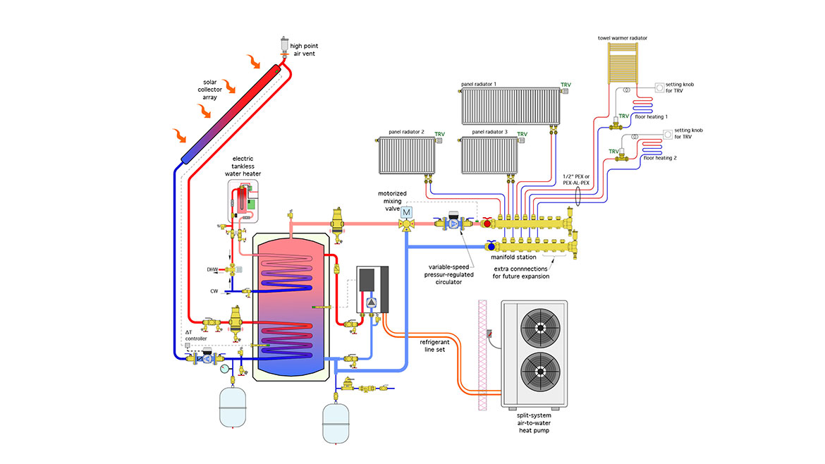
The heat pump provides supplemental heat input when needed, but its performance is more constrained compared to the boiler. To optimize the heat pump’s performance, the water temperature in the storage tank should be as low as possible but still able to provide the required heat output at the heat emitters. Outdoor reset control is ideal in this situation. Based on simulations I’ve done, the seasonal COP of the heat pump improves when this method of control is used in lieu of maintaining the tank temperature based on a setpoint high enough to fully heat domestic water to a delivery temperature of 120° F or higher.
Domestic water is “preheated” as it passes through the upper tank coil. A tankless electric water heater provides the final temperature boost, making this an all-electric system. All domestic hot water passes through the ASSE 1017 anti-scald valve before entering the building’s plumbing distribution system.
The motorized mixing valve is still needed if the heat emitters could be damaged or if uncomfortable or unsafe surface temperatures could be created when the tank is heated by the solar thermal collector to a temperature much higher than required.
Still viable
The “Solar DHW +” concept represents a “sweet spot” for active solar thermal technology that can coordinate well with low energy houses. The all-electric option shown in Figure 3 is especially well suited for homes aiming for “net zero” energy status. It’s worth keeping this concept in your renewal energy portfolio.
Looking for a reprint of this article?
From high-res PDFs to custom plaques, order your copy today!