John Siegenthaler: A persistent question
“But what do I do about cooling?”
The versatility of modern hydronics technology allows designers to create systems that are “customized” to the needs — and constraints — of almost any building. While best known for space heating, most modern hydronic systems for residential buildings also include provisions for heating domestic water.
Still, for many decades, one of the “shortcomings” of smaller hydronic systems has been the inability to cool buildings. This missing link has undoubtedly swayed many prospective clients away from hydronic systems, defaulting instead to ducted forced air because it provides both heating and cooling. Many of those decisions were made without factoring in the differences in comfort between these competing distribution systems.
This long standing inability to provide cooling is changing as the future of energy supply for heating continues to progress away from fossil fuels and toward electricity. This transformation is taking place in the two largest global markets for hydronics: Asia and Europe.
One example is Germany, arguably one of the bastions of hydronics technology, where incentives aimed at reducing fossil fuel usage have allowed electrically powered heat pump sales to challenge and, during one recent year, exceed boiler sales. Another example is China, where air-to-water heat pumps sales are now well over one million units per year.
For decades the trends in hydronic heating in these markets, especially European markets, have slowly but surely influenced market trends in North America. Examples include PEX tubing, condensing boilers, panel radiators and high efficiency circulators. The fundamental technologies used in these products all came from these markets.
If history is an indicator, the North America hydronics market is likely to see a major increase in the projects opting to use heat pumps rather than fossil fuel boilers. This transformation will bring the ability to provide chilled water cooling, and thus a more complete solution to comfort.
That’s a big deal in my opinion. It now allows hydronic heating pros to offer clients who increasingly look for cooling in new building construction, a solution that’s not a completely separate system. One that often gets installed by a different contractor.
Very doable
One approach I like to promote is multiple heating zones in combination with single zone cooling. The heating distribution system could use the same type of heat emitter in all zones, or it could use a combination of emitters.
An example would be radiant floor, wall or ceiling heating in some areas combined with panel radiators in other areas. Ideally, all heat emitters would be sized for the same supply water temperature. This keeps the system simple by eliminating the need for mixing.
Figure 1 shows a combination of heat emitters, all served by homerun circuits of 1/2-inch PEX, PE-RT or PEX-AL-PEX tubing from a common manifold station.
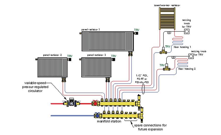
Flow to the manifold station is handled by a variable speed pressure-regulated circulator set for constant differential pressure. Each emitter is equipped with a non-electric (e.g., “wireless”) thermostatic radiator valve. That valve is built into the panel radiators. The only thing needed to make each panel radiator into an independently controlled zone is to screw a thermostatic operator onto that integrated valve.
The other two circuits show a combination of radiant panels and a towel warming radiator. Flow through these circuits is controlled by an external thermostatic valve equipped with a remote adjustment dial. That dial is typically mounted to a wall at normal thermostat height.
This combination of thermostatic valves provides five independently controlled heating zones. As these valves open, close or modulate flow, the variable speed circulator senses the “attempt” to change differential pressure, and immediately adjusts motor speed to cancel out that attempt. This allows the flow in each homerun circuit to remain stable, regardless of what zones are active.
The manifold station is shown with extra connections. This allows future emitters to be added with relative ease. It’s a relatively inexpensive up-sell that most clients would accept and see as professional forethought on your part.
Hot and cold
Figure 2 shows a low ambient air-to-water heat pump as the sole source of heating (and cooling) energy.
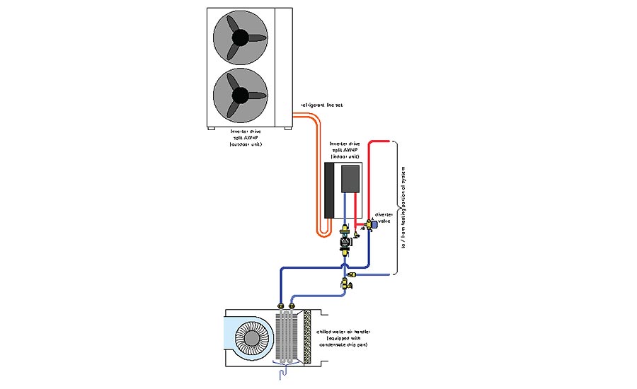
The heat pump is equipped with a variable speed inverter drive compressor. This allows it to modulate both heat output and cooling capacity down to about 40% of peak rating. The compressor speed changes based on maintaining user-specified leaving water temperatures for heating mode and cooling mode operation.
In most systems this allows the heat pump to supply an air handler sized to the building’s cooling load without use of a buffer tank — provided the air handler is not smaller than the minimum cooling capacity of the heat pump, and there is only one zone of cooling. Heat pumps with inverter drive compressors are also quieter than those with simple on/off compressors, especially at start up.
Since the heat pump is a “split system,” there’s no need to protect the outdoor unit from freezing, and thus the system can operate with water rather than an antifreeze solution.
The diverter valve directs flow leaving the heat pump to the heating or cooling portion of the system. It should be configured with its normally closed port, which is usually designated as “A” supplying the heating portion of the system, leaving the normally open port, which is usually designated as “B,” to supply the cooling mode.
The “A” port should only open when the heat pump is operating. This allows the diverter valve to prevent reverse thermosiphoning through what could otherwise be an unblocked piping path between the upper and lower portions of the tank. It eliminates the need for a check valve to otherwise prevent reverse thermosiphoning.
The air handler would supply a ducted distribution system. Since this portion of the overall system is for cooling, the ideal arrangement would put the outlet registers in the ceiling or high on the walls. This allows the cooled air to mix with room air without creating drafts.
In cold climates, it’s best to install the air handler in conditioned space. This all but eliminates the possibility of freezing water in the air handler’s coil during winter. It also reduces the potential for energy-wasting convective airflow through the air handler and ducting due to temperature stratification in the building.
If the air handler has to be mounted in unconditioned space, some means of freeze protection is required. The possibilities include draining the coil during winter, using anti-freeze in the system, building an insulated “dog house” enclosure around the air handler or installing heat tracing cable and hoping that no long duration power outages occur. I’m not a fan of any of these if they can be avoided.
Even small, residential scale air handlers can generate several gallons of condensate when operating on a humid day. Be sure to pipe up a condensate drain. Depending on applicable codes, this drain might be connected to the building’s DWV system, or it may have to be routed to a separate interior or exterior drainage point.
When the air handler is installed above a finished ceiling I recommend installing it over a secondary drain pan that would capture leaks from the air handler’s internal drip pan and route them to a suitable drain.
Thermal stabilizer
The final subsystem is a reverse indirect tank that provides buffering for the space heating zones, which typically have heat transfer requirements much smaller than the minimum heating capacity of the heat pump. The concept is shown in Figure 3.
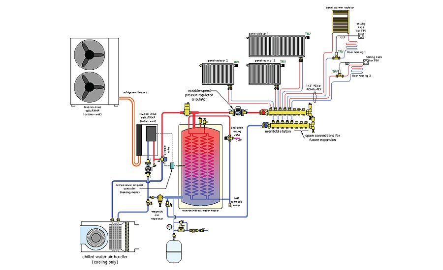
The tank piping is configured around one currently available reverse indirect. It’s a “2-pipe” configuration, which allows for “direct-to-load” heat transfer at times when the heat pump is running at the same time there is a space heating load.
One shortcoming of a 2-pipe tank configuration is a portion of the flow returning from the space heating load can pass through the heat source when it is not operating. This reduces heat transfer from the tank to the load. It also increases extraneous heat loss to the mechanical room, and lowers the mixed water temperature supplied to the space heating load. The latter occurs due to the two flow streams, one passing through the tank and the other through the heat source, and recombining upstream of the space heating circulator.
Fortunately, this can be prevented by ensuring the “A” port of the diverter valve, as shown in Figure 3, is only open when the heat pump
is operating.
The brains
During heating mode operation, the temperature of the buffer tank is monitored by a setpoint controller. When the sensor at the midpoint of the tank drops to some minimum value, the heat pump is turned on. This happens regardless of any demand for space heating. The goal is to keep the water in the tank’s shell warm enough to provide on-demand domestic water heating whenever there’s a draw at a fixture.
Once turned on, the heat pump continues to operate until the tank sensor reaches some upper limit. That limit should be several degrees Fahrenheit lower than the safety high limit setting programmed into the heat pump’s internal controller.
This is where a tradeoff needs to be made. The lower the temperature at which the buffer tank is maintained, the higher the heat pump’s coefficient of performance. However, for tank temperatures below about 115° F, the domestic water will only be “preheated” rather than fully heated.
Preheated domestic water will require a temperature boost prior to use at fixtures. That boost could come from a single electric on-demand tankless heater. It could also come from multiple smaller-capacity electric tankless heaters located close to each fixture or fixture group.
It’s also possible to base the buffer tank temperature on outdoor reset control. The warmer the outdoor temperature, the lower the buffer tank temperature. This keeps the water in the tank just hot enough to provide the building’s current heating load. Still, the lower the tank temperature, the greater the required boost in domestic water temperature leaving the tank.
The “optimal” temperature control for the tank must factor in the energy used for both space heating and domestic hot water, the COP of the heat pump operating over a range of both water temperature and outdoor temperatures, and the cost of electricity used for direct resistance heating. It would also factor in the cost of the hardware needed for temperature boosting. The math to figure this out is on my “to do” list, and I hope to report on it in a future column.
During cooling mode, the heat pump monitors its leaving water temperature and adjusts compressor speed to maintain a suitable setpoint, typically in the range of 45° to 50° F.
To ensure DHW availability, the system’s controls would give priority to maintaining the temperature in the reverse indirect tank. When the tank needs heating, the heat pump temporarily switches from chilled water mode to heating mode. The air handler blower can be kept on during this time. The time required to boost the temperature of the buffer tank during warm weather should be minimal because the heat pump is operating at high heating capacity.
When the tank reaches its upper temperature setting, the heat pump switches back to cooling. Keep in mind that most heat pumps have a built in time delay on compressor operation when switching modes, or when some control signal attempts to restart the compressor right after it was turned off. This allows the large differential pressure present across the compressor to dissipate prior to an attempted start.
It’s in your future
I encourage you to “read up” on air to water heat pumps. Their ability to provide cooling as well as heating and domestic hot water is a viable and cost effective solution to a question that’s been asked by many prospective clients desiring hydronic heating: “But what do I do about cooling?” Informed hydronic professionals are ready with an answer.
Looking for a reprint of this article?
From high-res PDFs to custom plaques, order your copy today!


