Design and use of check valves
Check valves protect both the suction and discharge sides of pumps, in addition to preventing backflow of possibly contaminated water.

In-line spring check valves have a spring loaded disk on a shaft that is located on the center-line of the piping system. Photo courtesy: NIBCO

The closure mechanism on a swing check valve is a disc attached to an arm that swings or rotates on a hinge outside the seat area. Photo courtesy: NIBCO
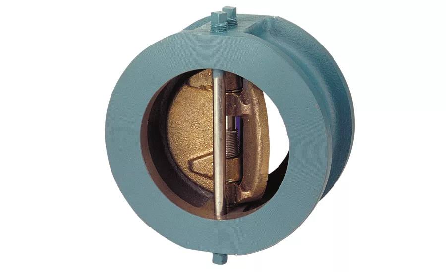
This variation of the swing check valve splits the disc into two D-shaped discs. With a double-disc swing check valve, each disc rotates on a shaft in the center of the waterway. Photo courtesy: NIBCO
Check valves are ubiquitous in all sorts of piping systems. Although they may be familiar to plumbing and mechanical contractors, the more than half dozen different types of check valves are designed for different functions and types of service. Contractors need to take care to select the correct check valves for the piping systems they are designing and installing.
The simplicity of the check valve should not hide the importance of its function or its potential to cause problems. Check valves are installed to protect piping systems, equipment and public health. Improperly installed check valves can result in costly repairs and system shutdowns.
Proper installation guidelinesThere are many additional factors to consider when designing a check valve into systems that were not covered here, including unclean media fouling the closing mechanism, hydraulic shock, turbulence, pulsating pressure and back pressure, to name a few. The following are a few guidelines to remember when specifying a check valve into your system.
|
Check valve application
The check valve is an automatic shut-off valve. Under pressure and flow, the closure mechanism opens, allowing the media to flow freely. When the flow and pressure stops, the closure mechanism returns automatically to the closed position, preventing the media from returning upstream.
The most common installation is at a pump. A check valve may be installed on the suction side of the pump to maintain the pump’s prime in the event of a pump shutdown. A check valve will be used commonly on the discharge of the pump to prevent backflow from the downstream system, when the pump shuts off.
Check valves are also used to prevent contaminated media in branches from flowing back into the main trunk line. The most common example is the use of backflow-prevention devices installed on any connection to a city water main. The backflow prevention device, a special form of check valve, prevents possibly contaminated water at a facility from flowing into the city water system when there is a sudden loss of water pressure in the main utility line.
Check valves rely on backpressure to affect a seal. The greater the backpressure the tighter the seal, but there is normally no stem to add mechanical pressure to guarantee the tightness of the seal. An elastomeric-sealing surface does not necessarily provide a bubble tight seal. Some backflow should always be expected through a check valve.
Check valve design
-
Swing check valve. The closure mechanism is a disc attached to an arm that swings or rotates on a hinge outside the seat area. The disc swings in a full 90° arc from fully opened to fully closed. Closure of the disc is caused by gravity pulling the disc and the reversal of flow pushing against the disc.
The swing check valve is a relatively slow closing valve, due to the distance the disc must travel to seat itself. Reversal of media flow begins before the valve closes. The advantage of the swing check valve is that it offers a full-flow waterway with minimal pressure drop across the valve. Many options are available on these valves, including a spring-assisted or weighted closure mechanism.
-
In-line spring check valve. These valves have a spring loaded disk on a shaft that is located on the center-line of the piping system. The spring keeps the disk in contact with the sealing seat but pressure and flow of the media will compress the spring to open the valve. These valves will always have a restricted flow of media due to the valve’s construction. The valve’s cracking pressure is quite low due to the relatively large area of the disk in the waterway.
-
Double-disc swing check valve. This variation of the swing check valve splits the disc into two D-shaped discs. Each disc rotates on a shaft in the center of the waterway. This reduces the path that the discs travel to effect closure. This short travel distance, along with springs attached to the disc, allows the check valve to close before the reversal of flow begins. The disc and pivot-pin obstruct the waterway and cause a greater pressure drop than a full-swing check.
-
Other valve types. Other types of check valve design include slant-disc check valve, lift check valve, rubber flapper check valve and diaphragm check valves.
Sizing tips
The common practice in piping is to size the check valve to fit the pipe size. The check valves, however, rely on flow and pressure to hold the closure member open. A buildup of pressure will open the flapper or poppet, but if the flow is not sufficient and continuous, the flapper will reseat. This fluttering causes premature wear and failure of the valve. Flow through a check valve should be sufficient to force the closure member firmly against the stop in the fully opened position.
Properly sizing a check valve requires matching an established minimum pressure drop (psi) to the actual flow (gpm) of the system. As a rule of thumb, the minimum pressure drop values for swing check valves are 0.5 psi and 2.0 psi for lift checks. The Guide for the Selection, Installation and Maintenance of Silent Check Valves by the Fluid Controls Institute recommends a 3 psi loss at normal flow for linear lift checks. At these pressure drops, the volume (gpm) varies, but the velocity remains around 10 feet per second.
The following is an example of how to use pressure drops to select the right size valve. Assume a 6-inch piping system with an average flow of 450 gallons per minute (velocity of 5 feet per second). Using this in a Cv formula (found on the flow data chart in the NIBCO Bronze and Iron Valve catalog):
1. Q = Cv √(ΔP/S)
Q = 450 gpm
ΔP = 0.5 psi or 3.0 psi (minimum)
S = 1 (specific gravity of water)
2. CV = Q/√(ΔP/S)
3. Determine the valve size by calculating the CV:
|
F-918 Swing Check ΔP = 0.5 |
F-910 Spring Check ΔP = 3.0 |
The F-918 with the closest Cv value in the catalog chart is the 4 inch. The F-910 with the closest Cv value is also the 4 inch. Note this is similar to sizing a stop check valve.
"This article was originally posted on ww.reevesjournal.com."
Looking for a reprint of this article?
From high-res PDFs to custom plaques, order your copy today!


