search
cart
facebook instagram twitter linkedin youtube
  • Sign In
  • Create Account
  • Sign Out
  • My Account
  • NEWS
  • PRODUCTS
    • FEATURED PRODUCTS
  • CONTRACTORS
    • BATH & KITCHEN PRO
    • BUSINESS MANAGEMENT
    • HIGH EFFICIENCY HOMES
    • TECHNOLOGY
    • WATER TREATMENT
    • PMC COLUMNS
      • Dave Yates: Contractor’s Corner
      • John Siegenthaler: Hydronics Workshop
      • Kenny Chapman: The Blue Collar Coach
      • Matt Michel: Service Plumbing Pros
      • Scott Secor: Heating Perceptions
  • ENGINEERS
    • CONTINUING EDUCATION
    • DECARBONIZATION | ELECTRIFICATION
    • FIRE PROTECTION
    • GEOTHERMAL | SOLAR THERMAL
    • PIPING | PLUMBING | PVF
    • PME COLUMNS
      • Christoph Lohr: Strategic Plumbing Insights
      • David Dexter: Plumbing Talking Points
      • James Dipping: Engineer Viewpoints
      • John Seigenthaler: Renewable Heating Design
      • Lowell Manalo: Plumbing Essentials
      • Misty Guard: Guard on Compliance
  • RADIANT & HYDRONICS
    • RADIANT COMFORT REPORT
    • THE GLITCH & THE FIX
  • INSIGHTS
    • CODES
    • GREEN PLUMBING & MECHANICAL
    • PROJECT PROFILES
    • COLUMNS
      • Codes Corner
      • Natalie Forster: Editorial Opinion
      • Guest Editorial
  • MEDIA
    • EBOOKS
    • PODCASTS
    • VIDEOS
    • WEBINARS
  • RESOURCES
    • INDUSTRY CALENDAR
    • DIRECTORIES
    • PM BOOKSTORE
    • CE CENTER
    • MARKET RESEARCH
    • CLASSIFIEDS
  • EMAGAZINE
    • EMAGAZINE
    • ARCHIVE ISSUES
    • CONTACT
    • ADVERTISE
    • PME EMAGAZINE ARCHIVES
  • SIGN UP!
Columns

Dueling Circulators
John Siegenthaler, PE

By John Siegenthaler, P.E.
May 1, 2005
Big surprises await those who use high flow-resistant, low-mass hardware into a traditional header-type piping layout.

Figure 1
One of the most popular methods of connecting multiple loads to a boiler is the classic “header system” as shown in Figure 1. The circulator for each circuit is fed from the higher temperature supply header, while returning flow is collected by the other header. The latter typically connects directly to the boiler inlet. For years this approach served the hydronics industry well. There are tens of thousands of such systems already installed with more going in every day.

Many of these classic header systems share common characteristics including:

  • They use a heat source with very little flow resistance. A good example being a cast-iron sectional boiler.

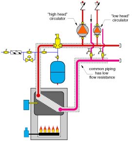
  • The “common piping” between the return header and supply header is relatively short and has very low flow resistance.

  • The zone circulators are either identical or closely matched in pumping ability.
These characteristics result in minimal interference between the different zone circuits as they turn on and off. Flow in one zone has virtually no effect on flow in other zones. This allows the thermal performance of each zone to remain relatively stable, regardless of which other zones are operating.

Unfortunately, many newly minted hydronic systems don't share this attribute. Instead, they use boilers with much higher flow resistance and less thermal mass relative to a cast-iron sectional boiler. The distribution systems these boilers serve often have six or more zones, some of which may be driven by high head circulators.

Big surprises await those who “cut and paste” such hardware into a traditional header-type piping layout. The resulting flow restrictions will cause some boilers to repeatedly “trip out” their internal safety switches due to unexpected temperatures or pressures. Water can flash to steam inside the boiler, causing noises that send most people diving for cover. Low flows in portions of the distribution system leave occupants shivering on the outside and steaming on the inside, especially when they remember the premium prices they paid for a modern high-efficiency comfort system.

Upon arriving for the inevitable callback, some installers try to fix these “glitches” by turning dials, typically in the upward direction. Rather than searching out the underlying cause of the problem, they try to overpower it with higher water temperatures. Most are bound to repeat the same elusive mistakes on future systems.

Figure 2

20/20 Hindsight

Consider the piping schematic shown in Figure 2. One of the pumped zones has a high head circulator, the other a standard 1/25 horsepower zone circulator. These pumps will tolerate each other's existence if the common piping between them has low flow resistance.

However, look at what can happen when the common piping has a high flow resistance. The situation is shown in Figure 3 using pump curves and the system curve for the common piping (which includes the boiler). The high flow resistance of the common piping in combination with the steep pump curve of the larger circulator creates a major pressure drop between the headers. For the case shown, the pressure drop is greater than the “stagnation” head of the smaller circulator. Thus, if the larger circulator is running at the same time as the smaller circulator, there will be no flow through the latter. The check valve in the circuit with the smaller circulator will be back-seated by the pressure differential established across the high flow resistance common piping.

Figure 3
Several years ago I discovered this by accident on a system that used a tankless coil heat exchanger mounted in a steam boiler as the heat source for a new hydronic floor heating system. The system used a high head circulator for the radiant distribution system and a typical 1/25 horsepower circulator for the indirect water heater. Whenever both circulators operated simultaneously, there was no flow through the indirect water heater. My first reaction was that something was wrong with the smaller circulator. I even took it apart thinking it was clogged or defective. After seeing that it ran fine when powered by a line cord, I reinstalled it only to find the flow problem remained.

It finally dawned on me that the problem wasn't the small circulator, but the large pressure drop setup across the tankless coil when the larger circulator was operating.

Fortunately, this was easy to correct by making the indirect tank a priority load. A simple relay was used to prevent the larger circulator from operating whenever the indirect thermostat called for heat.

This solution won't always be available or desirable, especially when several loads need to operate at the same time. A better solution is to pipe the high flow resistance heat source into the system as a secondary circuit, as shown in Figure 4.

Figure 4
This provides a dedicated circulator whose only purpose is to ensure adequate flow through the heat source whenever it operates, and without regard to the flow in the distribution system. Using “generously sized” headers on both supply and return provides minimal head loss in the common piping. I recommend sizing the headers for flow velocities of 2 ft. to 3 ft. per second under full flow conditions. The following table lists the corresponding flow rates for type M copper tubing.

Header size / Header flow rate
1-inch type M copper / 5.5-8.2 gpm
1.25-inch type M copper / 8.2-12.4 gpm
1.5-inch type M copper / 11.4-17.2 gpm
2-inch type M copper / 19.8-29.7 gpm
2.5-inch type M copper / 30.5-45.8 gpm
3-inch type M copper / 43.6-65.4 gpm

The supply temperature sensor for the boiler reset control should be downstream of the closely spaced tees, as shown in Figure 4. This allows it to sense the true supply temperature to the distribution system rather than the boiler outlet temperature. The temperature at this location accounts for mixing at the closely spaced tees when the distribution system flow rate is greater than the boiler flow rate.

Unnecessarily Concerned

The system shown in Figure 4 often operates with considerably more flow in the distribution system than through the boiler. This just doesn't feel right to those who've spent years installing classic header systems where all flow from the distribution system passes through the boiler. Fortunately, the first law of thermodynamics doesn't see this as a problem.

To understand why, you need to think in terms of Btus rather than gpm. The boiler produces heat at its rated output and puts that heat into the water passing through it. Doubling the flow rate through the boiler reduces the temperature rise across it, but has relatively little effect on the heat transfer rate.

The temperature of the distribution system will automatically rise or fall such that the rate of heat release by the heat emitters balances the rate of heat input from the heat source. That's the famous first law of thermodynamics at work. The fact that some of the distribution flow bypasses the closely spaced tees coupling the boiler to the distribution system doesn't change the fact that nature wants balanced energy flows.

If this distribution system happens to be running cooler than you expected, remember that it's only going to get hot enough to output the heat being delivered to it. If it can dissipate all the heat input at a supply temperature of say 110 degrees F, why would it want to increase to 115 degrees F, even if the aquastat on the boiler is set much higher - say to180 degrees F? The system doesn't care what you've set the aquastat to, it only cares about maintaining the balance between heat input and heat release.

The classic header approach still has a place in modern hydronics. However, when you're working with a low-mass boiler, play it safe with a primary/secondary interface between that boiler and the distribution system. Do the same for any component with high flow resistance that's located in the common piping of the header system. By doing so, you'll avoid bottlenecks in flow and let Mother Nature balance the energy flows to perfection.

Share This Story

Looking for a reprint of this article?
From high-res PDFs to custom plaques, order your copy today!

John siegenthaler 200x200

John Siegenthaler, P.E., is a consulting engineer and principal of Appropriate Designs in Holland Patent, New York. In partnership with HeatSpring, he has developed several online courses that provide in-depth, design-level training in modern hydronics systems, air-to-water heat pumps and biomass boiler systems. Additional information and resources for hydronic system design are available on Siegenthaler’s website,  www.hydronicpros.com.

Recommended Content

JOIN TODAY
to unlock your recommendations.

Already have an account? Sign In

  • 2025 Next Gen ALL-STARS hero 1440

    2025 Next Gen All Stars: Top 20 Under 40 Plumbing Professionals

    This year’s group of NextGen All-Stars is full of young...
    Plumbing & Mechanical Contractor
    By: Kristen R. Bayles
  • Worker using the Milwaukee Tool SWITCH PACK drain cleaner

    Pipeline profits: Drain cleaning, pipe inspection create opportunities

    Drain cleaning and inspection services offer lucrative...
    Green Plumbing and Mechanical
    By: Nicole Krawcke
  • Uponor employee, Arturo Moreno

    The reinvestment in American manufacturing and training

    Plumbing & Mechanical Chief Editor Nicole Krawcke and...
    Plumbing News
    By: Nicole Krawcke and Natalie Forster
Manage My Account
  • eNewsletters
  • Online Registration
  • Subscription Customer Service
  • eMagazine
  • Manage My Preferences

More Videos

Popular Stories

Hot water pipes

Campus shutdown at Oakland University exposes hidden risks of aging hot-water infrastructure

Floor heating manifold cabinet with flowmeter and PEX pipe.

Elegance extended: How to use the homerun system of connecting heat emitters

Industrial pressure gauge on a tank.

From cutting edge to classic: How to modernize outdated pneumatic control systems

Poll

Will business be up or down in 2025?

Do you anticipate business in 2025 to be up or down in comparison to 2024?
View Results Poll Archive

Products

The Water Came To A Stop

The Water Came To A Stop

See More Products
eBook | 2025 Radiant & Hydronics All Stars

Related Articles

  • A Tale Of Two Circulators
    John Siegenthaler

    See More
  • Picturing ∆P
    John Siegenthaler, PE

    See More
  • Plumbing connection with close up water brass thermostatic mixing valve isolated on white background.

    The Do's And Don'ts Of Three-Way Thermostatic Valves
    John Siegenthaler, PE

    See More

Related Products

See More Products
  • MHH4-cover-image-301x400.jpg

    Modern Hydronic Heating and Cooling For Residential and Light Commercial Buildings, 4th Edition

See More Products

Events

View AllSubmit An Event
  • May 29, 2014

    Coffee with Caleffi and John Siegenthaler: Air Source and Water Source Heat Pump Systems.

    Coffee with Caleffi will be hosted by John Siegenthaler on May 29, 2014.
  • January 24, 2014

    Webinar: How to Extend Lifecycles

    During the 30-minute presentation, executives from GPS Insight will discuss what you can do to stay on top of maintenance and control vehicle wear and tear. 
View AllSubmit An Event
×

Keep your content unclogged with our newsletters!

Stay in the know on the latest plumbing & piping industry trends.

JOIN TODAY!
  • RESOURCES
    • Advertise
    • Contact Us
    • Directories
    • Store
    • Want More
    • Supply House Times
  • SIGN UP TODAY
    • Create Account
    • eMagazine
    • eNewsletter
    • Customer Service
    • Manage Preferences
  • SERVICES
    • Marketing Services
    • Reprints
    • Market Research
    • List Rental
    • Survey/Respondent Access
  • STAY CONNECTED
    • LinkedIn
    • Facebook
    • Instagram
    • YouTube
    • X (Twitter)
  • PRIVACY
    • PRIVACY POLICY
    • TERMS & CONDITIONS
    • DO NOT SELL MY PERSONAL INFORMATION
    • PRIVACY REQUEST
    • ACCESSIBILITY

Copyright ©2025. All Rights Reserved BNP Media.

Design, CMS, Hosting & Web Development :: ePublishing