The USHGC: Putting the pieces together
The 2021 USHGC is one tool to help ensure high-quality radiant installations.

Photo courtesy of Philip Steury / iStock / Getty Images Plus
The Uniform Solar, Hydronics and Geothermal Code (USHGC) includes provisions for alternative energy sources for the transfer of energy in a hydronic system for space heating and cooling, or for other purposes such as snow and ice melting.
As we elaborated in Part 1 of this series, the sun’s energy can be used to power equipment with the use of solar photovoltaic (PV) systems, or to heat water or other fluids with the use of solar thermal systems.
Figure 1 illustrates how the solar PV system can be used to power the various components in a hydronic system.
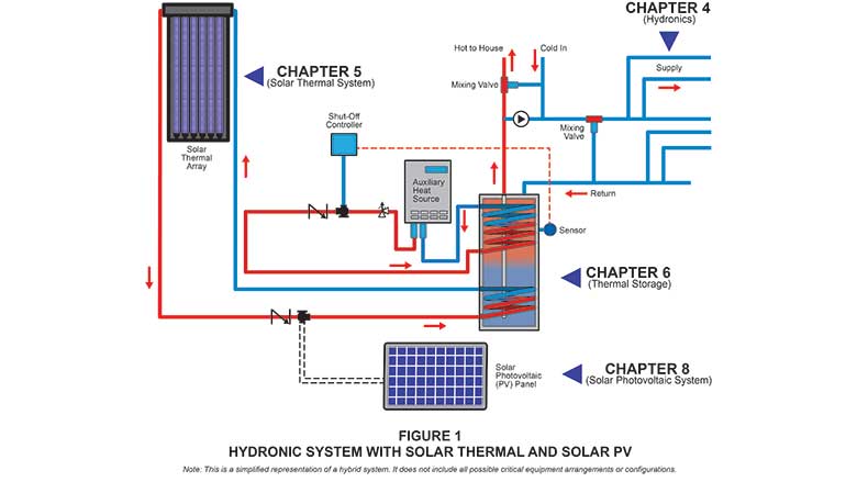
This article focuses on the hydronic system itself as covered in Chapter 4 of the USHGC, which applies to hydronic piping systems that are part of heating, cooling, ventilation, refrigeration and air conditioning systems. Such piping systems include steam, hot water, chilled water, steam condensate, condenser water, solar thermal systems and ground source heat pump systems. The regulations of this chapter shall govern the construction, location and installation of hydronic piping systems.
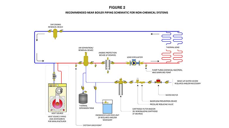
Figure 2 shows an example of a hydronic piping schematic.
Crucial hydronic provisions in the 2021 USHGC include:
Pressure And Safety Devices (Section 406.0)
406.0 Pressure and Safety Devices.
406.1 General. Each closed hydronic system shall be protected against pressures exceeding design limitations with not less than one pressure relief valve. Each closed section of the system containing a heat source shall have a relief valve located so that the heat source is not capable of being isolated from a relief device. Pressure relief valves shall be installed in accordance with their listing and the manufacturer’s installation instructions.
406.2 Discharge Piping. The discharge piping serving a temperature relief valve, pressure relief valve or combination of both shall be in accordance with Section 311.3.
Any heated closed-loop system is capable of developing pressures that exceed its design working pressure if certain devices malfunction. Pressure relief valves are necessary to prevent injury that could result from the failure of pressurized vessels and piping. Typical hydronic systems involve large complex piping circuits with valve arrangements that greatly increase the likelihood of portions of the piping system being isolated from the overpressure safety devices. Any portion of a system isolated from the relief valve or valves is unprotected from the danger of excessive pressures. Multiple relief valves at different locations in the system are necessary to ensure complete protection for all portions of a system.
A safety or relief valve discharge pipe is needed to direct the discharge to a location where it cannot cause injury or property damage. The material from which the discharge pipe is constructed must be able to withstand such pressures and temperatures, and be able to resist the forces developed during discharge that would tend to dislocate the discharge pipe. Section 311.3 of the USHGC addresses discharge piping materials, and additional provisions on discharge piping are referenced within Section 406.2 (Discharging Piping).
Prevention of oxygen ingress (Section 409.4)
409.4 Oxygen Diffusion Corrosion. PEX and PE-RT tubing in closed hydronic systems shall contain an oxygen barrier with an oxygen permeation rate not to exceed 4.59 E-04 grains per square foot per day (0.32 mg/m2/day) at 104°F (40°C).
Exception: Closed hydronic systems without ferrous components in contact with the hydronic fluid.
In closed-loop heating systems with any ferrous (e.g., iron or steel) components, the use of plastic tubing such as crosslinked polyethylene (PEX) or polyethylene of raised temperature (PE-RT) introduces the possibility that oxygen molecules from the atmosphere can permeate through the walls of the tubing and be absorbed into the hydronic fluid. Oxygenated fluid could lead to corrosion of ferrous components such as circulators, expansion tanks, and boiler heating elements. Therefore, PEX and PE-RT tubing in hydronic systems are required to have oxygen diffusion barrier layers to prevent this phenomenon. The German standard DIN 4726 was developed many years ago to establish a test procedure to demonstrate that plastic tubing has an effective oxygen barrier. The oxygen barrier limits of DIN 4726 are included in Section 409.4.
Insulation (Section 401.2)
401.2 Insulation. Surfaces within reach of building occupants shall not exceed 140°F (60°C). Where sleeves are installed, the insulation shall continue full size through them.
Coverings and insulation used for piping shall be of material approved for the operating temperature of the system and the installation environment. Where installed in a plenum, the insulation, jackets, and lap-seal adhesives, including pipe coverings and linings, shall have a flame-spread index not to exceed 25 and a smoke-developed index not to exceed 50 where tested in accordance with ASTM E84 or UL 723.
Insulation is required for the piping in a hydronic system to increase the efficiency of the system by slowing the heat transfer rate when surfaces exceed 140°F. This is also an important safety requirement, as temperature reaching more than 140°F can cause serious burn injuries to occupants and service personnel.
System controls (Section 411.0, Section 412.0)
System controls include water temperature controls where a water-temperature activated control is to be connected to heat sources to stop heat output where the water reaches a pre-set operating temperature. This is a crucial provision for protecting the hydronic system. Steam control is also important, and Section 411.2 of the USHGC requires a pressure-actuated control to be installed to shut off the fuel supply when the system reaches a pre-set operating pressure, and for the water level control to be installed where the water level falls below the required level by the manufacturer’s installation instructions.
The 2021 USHGC also addresses hydronic system such as:
Steam systems (Section 414.0)
The steam system requirements include the appropriate slope requirements of 1/8 inch per foot toward the steam boiler and direction of the steam flow, and air vents to eliminate pressure in the heat-distribution units for gravity steam piping systems.
Radiant heating and cooling systems (Section 415.0)
The radiant heating and cooling requirements include installation requirements, floor surface temperature limits, and language to prevent condensation on any cooled radiant surface as the supply water temperature for a radiant cooling system is required to be less than 3°F above the anticipated space dew point temperature, or in accordance with the manufacturer’s recommendation. Chilled water piping, valves, and fittings are required to be insulated and vapor sealed to prevent surface condensation.
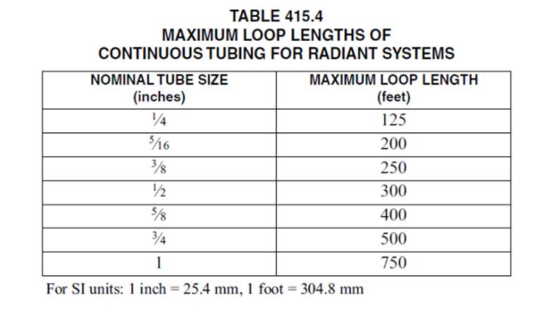
The maximum loop length of continuous tubing from a supply-and-return manifold shall not exceed the lengths specified by the manufacturer or, in the absence of manufacturer’s specifications, the lengths specified in Table 415.4.
Snow and ice melt systems (Section 417.0)
The snow and ice melt system requirements found in the USHGC provide the appropriate safety provisions for a snow and ice melt system, which are intended as safety systems to prevent snow- and ice-covered outdoor surfaces. It addresses the use of chemical additives, corrosive fluids, and snow and ice melt controls as shown below in Section 417.2. Section 401.5 requires that terminal units and flow control devices be installed in accordance with the manufacturer’s installation instructions.
417.2 Snow and Ice Melt Controls. An automatic operating control device that controls the supply hydronic fluid temperature to the snow and ice melt area shall be installed in the system. A means shall be provided to prevent low return hydronic solution temperature in accordance with Section 401.5. Snow and ice melt systems shall be protected from freezing with a mixture of propylene glycol and water or other approved fluid. Automotive antifreeze shall not be used.
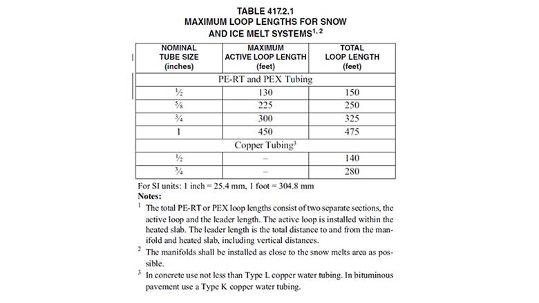
The maximum loop length of continuous tubing from a supply-and-return manifold arrangement is not to exceed the lengths specified by the manufacturer or, in the absence of manufacturer’s specifications, the lengths specified in Table 417.2.1.
The USHGC should be an important tool for designers, installers, manufacturers and inspectors of the systems it covers. Never has an ANSI code gone into so much detail about specific requirements for hydronic heating and cooling systems, specifically on the radiant heating and cooling side, plus hydronic snow and ice melting.
“The 2021 USHGC Technical Committee included a wide range of expertise on all the systems covered in this code, from contractors to inspectors, manufacturers and certification bodies. TC members relied on each other’s experience to complement their knowledge. “It was a great experience chairing this group of experts,” said Lance MacNevin, P.Eng., the director of engineering from The Plastics Pipe Institute (PPI) and chairman of the 2021 USHGC.
The code includes the critical installation requirements to help make these hydronic systems safe and efficient, and requirements are written using enforceable language so that the inspector does not necessarily need to have decades of hydronic experience to ensure that these minimums are adhered to.
The code is not a design guide, and designers, contractors and installers should still seek competent professional training related to their scope of work in hydronics. However, code requirements can help all those involved to avoid serious and costly mistakes.
Why Is The Radiant Professionals Alliance (RPA) Behind These Code Additions?
There are many competent hydronic designers and installers whose systems already meet or exceed the requirements of the USHGC. Many of these professionals are already members of the RPA and have been working for decades to improve the level of hydronic installations across the country, since the quality of hydronic systems is imperative for customer satisfaction and safety, especially with radiant systems where tubing is embedded in concrete floors and can’t be adjusted or repositioned. For the long-term success of hydronic radiant heating and cooling, with a goal of widespread acceptance like we see in Europe, regions of Canada and other countries, quality of installations needs to be at a consistently high level. The 2021 USHGC is one tool to help ensure this goal.
Many provisions of the 2021 USHGC concerning radiant heating and cooling applications have not appeared in model codes before; the RPA’s involvement in the development of relevant language ensures that state-of-the-art design and construction principles are considered.
All images courtesy of IAPMO.
Looking for a reprint of this article?
From high-res PDFs to custom plaques, order your copy today!


.jpg")