The heart of the radiant hydronic system
A radiant system always has a supply and a return manifold.
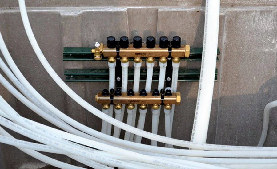
A 6-loop TruFLOW brass manifold supplies a water/glycol mix to the snow-and ice-melt system at the light rail station in Ramsey, Minn. Photo courtesy of: Uponor
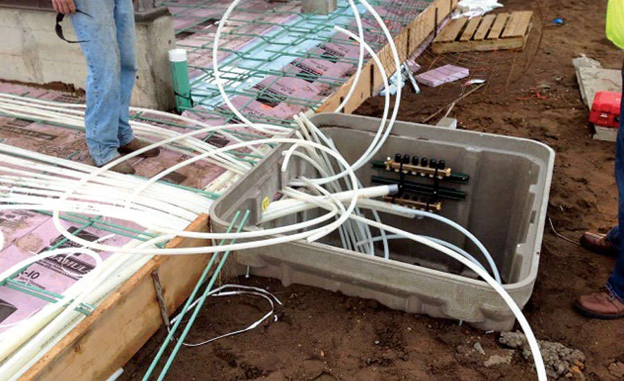
Six manifold boxes placed every 85 feet along the edge of the light rail platform house a total of 20 TruFLOW brass manifolds. Photo courtesy of: Uponor
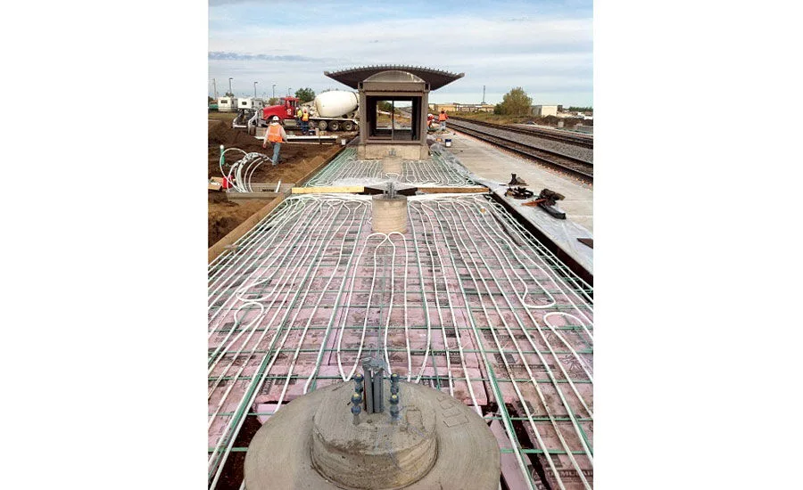
The Ramsey, Minn., light rail project uses 48,000 feet of ¾-inch Wirsbo hePEX tubing placed 6 inches on center for the snow- and ice-melt system. Photo courtesy of: Uponor
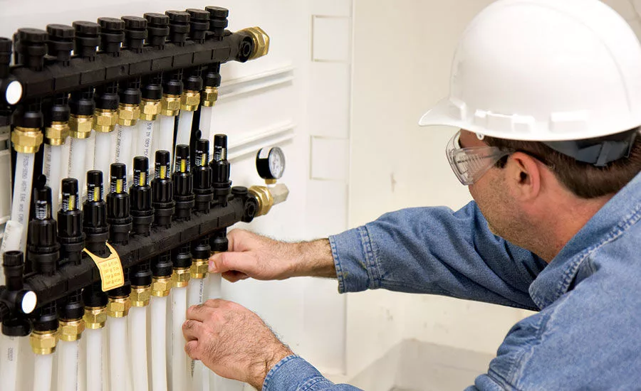
A nine-loop engineered polymer (EP) manifold in a manifold wall cabinet manages the supply and return water for a hydronic radiant system. Photo courtesy of: Uponor
The turf conditioning system at Toyota Park features copper manifolds connected to 150,000 linear feet of ¾-inch Wirsbo hePEX tubing spaced 8 inches on center. Photo courtesy of: Uponor
Every hydronic radiant system — whether radiant heating (or cooling), snow/ice melting, turf conditioning or permafrost prevention — has four main components:
-
Radiant tubing (preferably with an oxygen barrier to protect ferrous components in the system);
-
A heating (or cooling) source;
-
Manifolds; and
-
Controls.
Granted, there are accessories that go into a hydronic radiant installation, depending on the application — for example, clips, staples or tie downs, heat-transfer panels, etc. But it’s important to understand the four key components first to ensure the basics are met for a high-performing system.
Manifolds are the heart of the system, distributing the heated (or cooled) water (or water/glycol mix) throughout the tubing, or “veins,” of the system. When designing a radiant system, the first step is determining how much heating or cooling load the space has, then correlating the water temperature and flow rate to handle that load.
A radiant manifold receives water (at the right temperature for the installation), and divides the water into loops with the appropriate flow rates. A radiant system always has a supply and a return manifold. The supply manifold distributes the water out to the radiant loops to heat or cool the space. As the water flows through the loops, it loses heating (or cooling) capacity, as it moves to the return manifold to go back to the heating (or cooling) source.
Manifold features
Manifolds can be simple or complex, depending on the application.
-
They can have flow meters, which allow adjustment of the volume — measured in gallons per minute (gpm) — through the individual loops of the radiant system;
-
They can have actuators, which turn individual loops and/or zones on and off;
-
They can feature a temperature gauge to show the temperature differential between the supply and return water temperature;
-
They can include ball valves to shut off the entire manifold as well as all the loops tied to that manifold; and
-
They can also feature manual or automatic air vents and fill-and-purge ports, which are used during commissioning (i.e., initial startup) of a radiant system.
Radiant manifolds have evolved over the years. Earlier versions required onsite assembly of the parts and pieces before installation. Now, contractors can simply take the manifold out of the packaging, mount it on a wall or in a manifold cabinet and attach the tubing.
Manifolds are available in a variety of shapes and sizes to accommodate various installation applications. They can come in two- through 12-loop configurations with the most common being four to six loops. Some modular manifolds can also accommodate additional add-on loops, if necessary.
Manifold types
Most manifolds in today’s systems are “pre-assembled,” with the supply and return together in one assembly. There are brass, stainless steel and engineered polymer (EP) versions that offer various barrel sizes, gpm, and temperature and pressure capacities.
For example, the TruFLOW brass manifold offered by Uponor comes in a 1-inch or 1¼-inch barrel with two through 12 loops and accommodates 21 gpm with a temperature/pressure capacity of 194° F at 145 psi. There is also an EP manifold that features a 1-inch barrel with 2- through 8-loop configurations, accommodates 15.4 gpm, and can handle a maximum temperature of 194°F at 44 psi.
HDPE (high-density polyethylene) “unassembled” manifolds are typically used for direct-burial applications, such as turf conditioning or permafrost prevention. Copper manifolds tend to be used for higher-flow custom applications.
Now that you’ve learned all the basics of radiant manifolds, let’s take a look at some of these workhorses in action.
Minnesota commuter rail platform
The Northstar commuter rail in Ramsey, Minn., a suburb northwest of Minneapolis, consists of two main passenger platforms and a pathway to a large parking garage. Each platform is 425 feet long and 26 feet wide with a snowmelt system embedded in the concrete to keep commuters safe from slipping in the icy, snowy Minnesota winters.
The system is designed for a 50% water/glycol solution, which is heated by a high-efficiency boiler. This solution circulates through PEX tubing buried in the concrete to heat the station surface until it is warm enough to melt snow and ice.
“We laid down a total of 48,000 feet of ¾-inch Wirsbo hePEX tubing placed 6 inches on center,” says Greg Koba of Klamm Mechanical in Burnsville, Minn. “We then placed six manifold boxes every 85 feet, housing a total of 20 TruFLOW Jr. manifolds.”
In addition to the ¾-inch tubing, there are also eight 2-inch PEX main lines for each platform that run from two manholes in the landscape area, and then enter the slabs and stub into the manifold boxes. The two manholes connect through a 16-inch jacket housed underneath the track that also holds the two, 4-inch main lines that supply the platform.
“One of our biggest concerns was to ensure that the supply and return piping to the manifolds did not compromise the structural needs of the system,” Koba says. “By using large-dimension tubing to feed all the manifolds, we were able to route the system efficiently and correctly.”
California student union
San Diego State University’s student union, the Aztec Center, is a highly sustainable, LEED Platinum, three-story building designed to house student offices, a recreation center and an intercultural relations center. It also includes a 1,200-seat lecture hall and a 300-seat theatre.
The 202,000-square-foot structure incorporates a number of energy-saving features that make the building more energy-efficient. The HVAC system, designed to consume 40% less energy than standard systems, includes an in-slab radiant heating and cooling system. The latter is coupled with a dedicated outside air system (DOAS) to reduce energy consumption and improve indoor air quality.
The installing contractor, San Diego-based University Mechanical, installed 75,000 feet of 5/8-inch Wirsbo hePEX tubing on three floors on the west side of the building to serve 36,000 square feet of space, including dining and lounge areas on the first floor and meeting and office spaces on the second and third floors. The tubing was spaced 6 inches on center and fed by 21 EP manifolds. The chilled and heated hot water is supplied from the campus central utility plant.
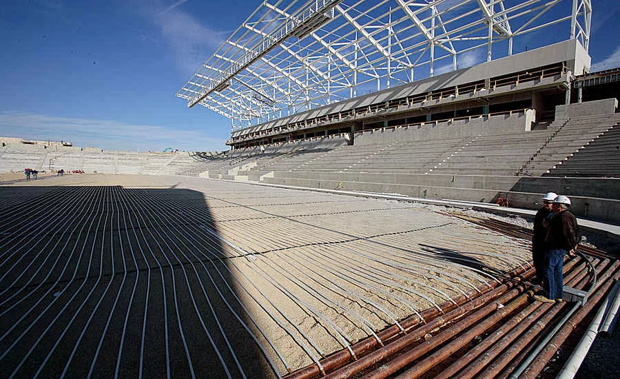
Illinois Professional Soccer Stadium
Toyota Park in Bridgeview, Ill., is the fourth major soccer-specific field in the U.S. It features a turf-conditioning system that circulates a water/glycol mixture through PEX tubing buried underground to warm the root zone beneath the grass, so the playing surface remains soft and forgiving, even at sub-freezing temperatures.
According to the project supervisor, Chris Bennett of Althoff Industries in Crystal Lake, Ill., the radiant heating system consists of roughly 28 miles (nearly 150,000 linear feet) of ¾-inch Wirsbo hePEX tubing that serpentines from end zone to end zone, 8 inches on center and 10 inches below the 200-foot by 425-foot playing surface.
The tubing connects to copper manifolds positioned at the south end of the field. Like the interior of a home or a large office, the field is segmented into four heating zones, also running the length of the field from goal to goal. Each zone contains 42 loops and two temperature sensors that sit within underground boxes connected to one another with plastic conduit. If any underground sensors ever need to be repaired, all eight are on GPS, enabling service personnel to pinpoint the positions of the underground boxes to within 18 inches.
On sunny days, the demand for warmth varies from zone to zone, depending on the position of the sun. The sensors in each zone communicate an average demand back to a series of control valves, which modulate the flow of warm water in response. The objective is to keep the root system at a consistently comfortable 65° F, says Bennett.
“The field is warm and moist enough that it can actually grow grass in December or even January,” he remarks. “The freezing point for the glycol mixture is minus 25°, so the system can be filled with fluid year-round, without the hassle and expense of draining and re-filling it prior to each season.”
What are manifold wall cabinets?
A manifold wall cabinet is a recessed-style box installed between two-by-four or two-by-six stud walls to house manifolds. They provide fast and easy access for maintenance and troubleshooting purposes after the system is up and running.
Wall cabinets typically house manifolds with up to 12 loops, and they can also usually house other components, such as zone control modules for ease of wiring and protection from damage.
The cabinets come in various configurations, depending on the manufacturer. Some are approximately 36 inches high with varying widths of 24 inches to 39 inches and about 3½ inches in depth. They can also feature a lockable door for security purposes to prevent tampering with, or damage to, the inside equipment.
Looking for a reprint of this article?
From high-res PDFs to custom plaques, order your copy today!


.jpg")