The Glitch & Fix: Multiple boiler blues


The Glitch:
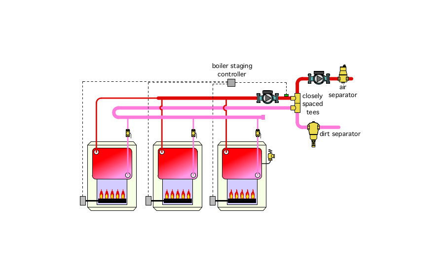
A multiple boiler system is set up as shown in Figure 1. The objective is to add heat to the system in three on/off stages. Can you find some problems with this layout? Can you think of ways to simplify it?
Figure 1:
The Fix:
The system shown in Figure 1 could work, but it uses more materials and wastes more energy than necessary.
The “cardinal rule” of modern multiple boiler systems is to only allow flow through boilers when they are firing. Allowing flow of heated water through unfired boilers, which would occur in the system shown in Figure 1, simply dissipates heat through the boiler jacket and by convection up the flue.
It’s also unnecessary to use reverse return piping if the header system can be designed for low head loss.
There is no valving for isolating each boiler from the balance of system if necessary.
Another problem is the location of the supply temperature sensor. The boilers should be controlled based on the temperature going to the distribution system. This should be sensed downstream of the distribution circulator. The reason is mixing at the closely spaced tees. If the distribution system flow rate and boiler system flow rates differ, there will be mixing at these tees, and that causes a change in supply temperature. The sensor has been moved to the proper location in Figure 2.
Figure 2:
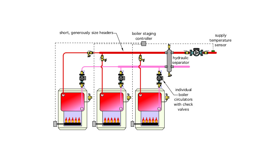 The revised layout uses individual boiler circulators with integral check valves. Each circulator operates when it associated boiler is firing and remain off at other times.
A hydraulic separator replaces the closely spaced tees, the air separator and the dirt separator. It installs faster than these individual components and takes up less space in the mechanical room.
The reverse return piping has been eliminated. The short and generously sized headers create very little head loss. The flow rates through each boiler may not be identical — but they will be very close — and any variation will be on no concern.
Purge valves have been added to the output piping of each boiler. These valves, in combination with the isolation flanged on the circulators, allow each boiler to be isolated if necessary.
All circulators should have a means of isolation. Full port ball valves have been added to each side of the distribution circulator.
Finally, each boiler must have its own pressure relief valve.
Download The Glitch and Fix: September 2020 in pdf form.
Looking for a reprint of this article?
From high-res PDFs to custom plaques, order your copy today!


.jpg")