
To some, the answer seems obvious: Pipe the tank as a secondary circuit off the primary loop. After all, I've just been telling them that P/S piping is one of the best concepts to come along since round wheels!
To others the fact that the question is even asked makes them think the answer may not be so simple. Perhaps this is one of those "trick questions" speakers like to throw at audiences.
As with many questions regarding hydronic heat there is no one absolute right answer. Instead, there are tradeoffs that must be evaluated in pursuit of a stated objective. In this case, that objective is to move heat as efficiently as possible from the boiler into the DHW tank.
Let's dissect each of two popular piping approaches in light of this objective:
The First Secondary
The schematic in Figure 1 shows the indirect tank piped as a secondary circuit.Notice that the indirect is connected upstream of any secondary circuits serving space heating loads. This ensures the tank's heat exchanger gets the hottest water available when operating. The hotter the water supplied to the tank's heat exchanger, the faster the tank heats domestic water.
Also take note of the flow-check valve installed in the secondary riser leading to the tank. It's there for two reasons. One is to prevent the slight pressure drop between the closely-spaced tees from generating a trickle of hot water through the tank's heat exchanger when the tank is not being heated.
At one time, I felt a small migration of hot water through the tank's heat exchanger might compensate for the tank's standby heat loss. This in turn might reduce the number of times the boiler fired to make up for these losses. However, after hearing of several instances where a slow migration of hot water through the heat exchanger overheated the tank to the point of opening its P&T relief valve I gave up on this idea. By the way, this heat migration can occur in systems where the secondary piping goes down from primary loop. In this case a thermal trap is not an acceptable substitute for the flow-check.
Another duty of the flow-check is to prevent a reverse thermosiphon flow from the tank's heat exchanger through the secondary piping and closely spaced tees. In the absence of the check-valve, reverse flow will occur due to the combination of hot water in the tank's heat exchanger, and the unblocked piping path leading upward through the closely spaced tees and back down to the tank. Nature will set up a convective loop to dissipate heat from the tank whenever the secondary piping drops to a temperature lower than that of the tank water. The weighted plug in the flow-check valve not only stops forward flow due to the slight pressure drop between the tees, it also prevents reverse flow after the piping cools off.
A significant drawback of this piping arrangement is that hot water must flow completely around the primary loop whenever heat is delivered to the indirect tank. Water leaving the tank's heat exchanger is still relatively hot, and its only way back to the boiler is through the remainder of the primary loop.
If the primary loop is relatively short, stays within the mechanical room, and is insulated, the piping heat loss can be minimized. However, imagine a system in which the primary loop is routed through a portion of the building, perhaps to service several remote secondary circuits. Such a loop has the potential to dissipate a considerable amount of heat into the building.
Here's an example: An uninsulated 1-inch copper piping loop 120-ft.-long, operating with an inlet temperature of 160 degrees F and a flow of 10 gpm would deliver over 6,300 Btu/hr. to a basement at 65 degrees F. That loop also contains about 5.5 gallon of water. Each time the DHW cycle occurs the water in the loop requires about 4,300 Btus to get up to a nominal 160 degrees F. At the end of each cycle this heat is dissipated to the surrounding air.
One could argue that heat released from piping provides part of the space heating load. However, there's no guarantee that heat lost from the primary loop will be delivered when and where it's needed for space heating. Furthermore, during warm weather this heat loss only adds to the building's cooling load.
In light of this, I recommend that indirect water heaters be piped as secondary circuits only when used in conjunction with short primary loops that are contained within the mechanical room and preferably insulated.
The piping shown in Figure 1 will also cause a drop in the water temperature supplied to downstream secondary circuits if the tank is operating as a non-priority load. I feel the best solution to this is to control the indirect as a priority load. All other loads served by the primary loop would be temporarily turned off during the DHW heating cycle.

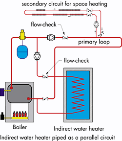
Parallel Perks
The schematic shown in Figure 2 pipes the indirect water heater as a parallel rather than secondary circuit. There are some significant advantages to this approach.First of all this approach eliminates the need to operate the primary pump during the DHW heating cycle. Why run two circulators when one can do the job just fine?
Since the primary loop is not operating during the DHW cycle, it doesn't dissipate heat into the building.
Finally, this approach doesn't cause a drop in the primary loop temperature upstream of the other secondary circuits in systems where space heating and DHW heating may operate simultaneously.
When using the parallel circuit layout it's imperative to install a flow-check in both the primary and DHW circuits. Without the valves there will be flow reversal through either the primary loop or the DHW loop when one is on and the other is off. I also like to install a third check valve, usually a swing check, on the return side of the primary loop upstream of where the DHW circuit tees in. This prevents heat migration into the return side of the primary loop.
If you're using a multiple boiler system I suggest the piping shown in Figure 3. The P/S tees allow the DHW circulator, as well as other secondary circulators, to operate without interfering with the boiler circulators.
Be sure not to create any "bottlenecks" to heat transfer between the multiple boiler system to the DHW tank. The objective is to move all the heat the boiler system can produce into the DHW tank. Pay close attention to pipe and circulator sizing.
Set up the controls for DHW priority on this type of system. With all that boiler power ready to go why not allow the system produce DHW as fast as possible? Especially with all those thirsty showerheads and whirlpool baths waiting upstairs.
When all things are considered I feel that parallel rather than secondary piping is the better way to pipe an indirect in an otherwise P/S system. It better meets the objective of moving heat from the boiler into the DHW tank as efficiently as possible.

