Examining the effects of flow reversal in circulators
Unique design concepts sometimes require components to operate in non-standard conditions.
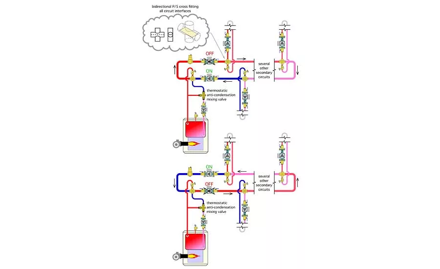
Figure 1. One example is periodic flow reversal through a circuit with several series-connected secondary loads, such as in Figure 1.
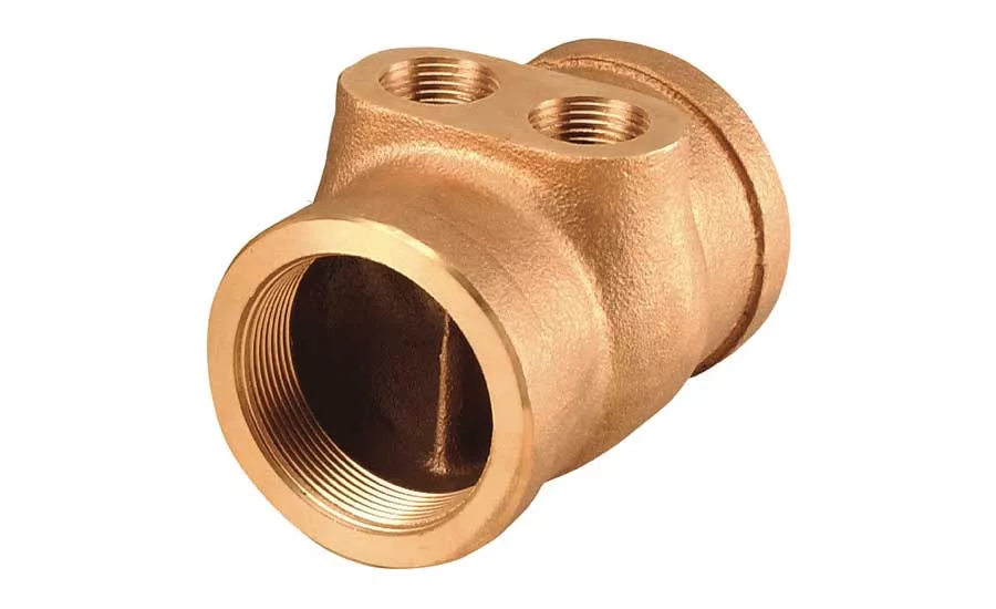
Figure 2. “Twin-Tee” fitting from Taco.
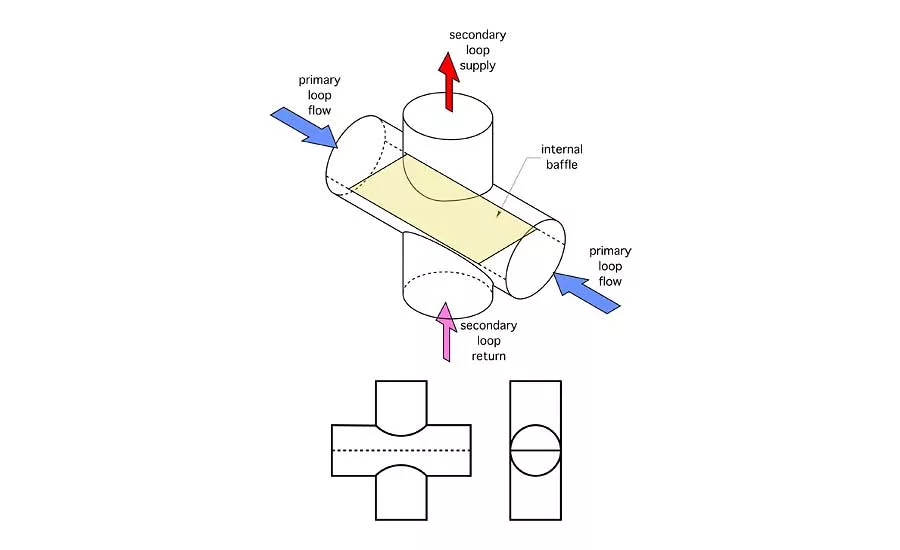
Figure 3. Another possibility would be to fabricate a fitting by brazing a baffle plate into a cross fitting, as illustrated in Figure 3.

Figure 4 shows a possible piping configuration.
Unique design concepts sometimes require components to operate in non-standard conditions.
One example would be using balancing valves to regulate flow through multiple banks of solar collectors in a large drainback solar thermal system. In a more typical solar thermal system operating with antifreeze, the use of balancing valves would be routine. But in a drainback system, there is no antifreeze. Water drains out of the collector array and exterior piping whenever the collector circulator turns off.
If balancing valves are installed in this portion of the system, they will be subject to thousands of freeze/thaw cycles over the life of the system. Any residual water within the valve will surely freeze. Would this cause any long-term damage to that valve? Designers need answers to such questions before specifying products. Manufacturers might or might not have those answers.
Changing Direction
There are hydronic design concepts in which flow must pass backward through a non-operating circulator, perhaps thousands of times over the life of the system. One example is periodic flow reversal through a circuit with several series-connected secondary loads, such as in Figure 1.
This system relies on a specific type of fitting where the secondary circuits, including the boiler circuit, connect to the primary loop. One source of such a fitting is Taco. They call it a “Twin-Tee.” Figure 2 shows an example of this fitting.
Another possibility would be to fabricate a fitting by brazing a baffle plate into a cross fitting, as illustrated in Figure 3.
Primary flow can enter the run of these fittings from either direction. However, the flow direction through the secondary circuit will not change. The internal baffle prevents direct mixing between the supply and return sides of the secondary circuit. The supply and return ports for the secondary circuit are also located at the same pressure location along the primary circuit, which provides excellent hydraulic separation.
Periodic flow reversal through the primary loop would, over time, provide the same average supply water temperature to each secondary circuit. This corrects for the inherent drawback of decreasing supply water temperature in circuits where multiple loads are connected in series. The greater the design temperature drop along the primary loop, with all circuits operating, the greater the benefit of periodic flow reversal.
The operating logic for the system shown in Figure 1 is simple: One primary loop circulator operates for a given time; it then shuts off and the other primary circulator operates for the same elapsed time. A duplex circulator controller could be used to keep track of the running hours on each primary loop circulator and equalize them over time. Primary loop flow would always pass backward through the circulator that’s off.
Up, down, up down
Another application where flow reversal is useful is when a coil heat exchanger within a thermal storage tank is used for both heat input and heat extraction. Flow reversal would be necessary to preserve temperature stratification within the tank and maximize the average temperature difference at which the heat exchanger operates. Figure 4 shows a possible piping configuration.
The upper piping assembly in Figure 4 shows heat being added to thermal storage. The load circulator could be on or off. If on, it draws hot water coming from the heat source at point A. Any flow not pulled to the load passes through the hydraulic separator and downward through the coil heat exchangers.
The tees where the load circuit connect to the system, (e.g., points A and B in Figure 4) should be kept as close to the hydraulic separator as possible. To prevent mixing within the hydraulic separator, the flow rate from the heat source should always be equal to or greater than the flow rate created by the load circulator.
The lower piping assembly in Figure 4 shows heat being extracted from thermal storage and sent to the load. Flow is now passing from the bottom of the coils to the top, optimizing the temperature differential across the coils. If the heat source turns on, the flow would reverse.
Figure 4 also shows two electrically operated valves in parallel with the coil circulators. These could be zone valves or motorized ball valves. When one of these is turned on, it channels some flow from the coils around the adjacent circulator that’s off. This reduces the reverse flow through that circulator. These valves should have high Cv ratings to minimize pressure drop.
Questions remain
Although the piping configurations shown are rational solutions for accomplishing reverse flow, there are still several questions that need answers. For example: Is it even necessary to have the two motorized valves shown in Figure 4? If they were eliminated, all flow from the coils would pass backward through the circulator that’s off. Eliminating these valves would obviously be simpler and less costly, but would routing all coil flow backward through the circulator create any problems? Another possibility would be to install check valves in both circulators to prevent any reverse flow and have all flow pass through the motorized valves. Which of these approaches is better?
To help answer such questions, we need to know more about reverse flow through the circulators. Here are a few more questions in that regard:
-
What is the head loss versus flow rate when flow is moving backward through a specific circulator?;
-
Could any conditions develop that would be harmful to a circulator when flow is passing backward through it? For example, is there any possibility that an impeller that is treaded to the motor shaft could unscrew itself if subject to reverse flow over a long time?; and
-
Could reverse flow through a circulator with an ECM motor cause the impeller to spin backward and spin the permanent magnet rotor within the stator poles and induce an electrical generation effect?
These questions could be answered by installing a circulator in a test stand and forcing flow through it in reverse and at different flow rates. Data for flow versus head loss could be captured and plotted. The resulting curve could then be used to assess the parasitic head loss characteristic of the circulator. This would help answer questions such as: Are the motorized valves shown in Figure 4 essential or just a waste of money and material?
Any potential electrical feedback could also be assessed during such a test.
A final plea
Let me close the column by politely asking any circulator manufacturer who reads this to consider doing reverse-flow testing on some of their circulators and making specific recommendations based on the results of those tests. Having this support would help refine designs for hydronic assemblies such as those we’ve discussed. I would welcome further discussion on the subject.
This article was originally titled “What happens when…” in the February 2017 print edition of Plumbing & Mechanical.
To read the article in pdf form, please see here.
Looking for a reprint of this article?
From high-res PDFs to custom plaques, order your copy today!


.jpg")


