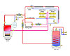
The schematic shown here (right) is based on a sketch recently forwarded to me. The system is supposed to provide radiant floor heating to the first and second floors of a building. The basement is heated by fin-tube baseboard.
Other loads include domestic water heating using an indirect tank, and a circuit of tubing located near the building’s footing, which is to prevent frost heaves in the very cold climate where this building is located.
Given these requirements, how might you redesign this system?
The Glitches
There are several things wrong with the original layout:1.There will be very little flow to the radiant floor circuits given the way they are piped. The vast majority of the flow created by the circulator will simply bypass the relatively high hydraulic resistance of the radiant floor circuits and flow through the low resistance “bypass” piping.
2.The single three-way thermostatic mixing valve does not protect the conventional boiler from low-temperature return water. This will lead to sustained flue gas condensation and corrosion in the boiler and its vent piping.
3.The coil in the indirect water heater is piped in reverse. Hot water from the boiler should enter the upper coil connection to provide counterflow heat exchange within the tank.
4.The diverter valve at the top of the schematic is supposed to allow or prevent flow through the baseboard circuits. However, it is not piped properly. The hot water should enter the “common” (AB) port. The B port should connect to the bypass line, and the A port to the baseboard supply. Ultimately, it would be easier to just eliminate this valve and use another circulator to handle the baseboard zone.
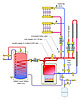
The Fixes
The corrections I’m suggesting are shown here (right):1.The cast-iron boiler has a very low head loss characteristic. When combined with low loss supply and return headers, there is good hydraulic separation between the various load circulators. This eliminates the need to use a primary / secondary loop.
2.I also opted for a motorized three-way mixing valve, which has the “smarts” to properly protect the boiler from sustained flue gas condensation when necessary. The two manifold stations are connected in parallel along with a flow balancing valve with visual flow indicator on each station. No differential pressure control is needed since both manifold stations operate as one zone.
3.The piping of the coil heat exchanger within the indirect water heater has been corrected.
4.Purging valves have been added to each load circuit.
5.A microbubble air separator has been added. It is piped such that flow from the boiler passes through it during both space-heating and domestic water-heating modes.
6.Insulation has been added to the piping used for the DHW mode. This reduces unwanted heat loss during nonspace-heating periods.

