The Glitch
The Glitch
Overview:During the last three years, a new hardware device has been showing up in more American hydronic systems. It’s called a hydraulic separator, and it’s now available in a range of sizes from several manufacturers.Hydraulic separators provide an alternative to closely spaced tees when the task is to isolate the pressure dynamics of one hydronic circuit from those of another, connected circuit.
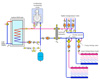
Eager to keep up with this new technology, an installer decides to install a hydraulic separator between a boiler and distribution system as shown in the figure below. Some of the load circuits connected to the hydraulic separator are piped “across the headers,” while others are connected with closely spaced tees. All the load circuits are supposed to operate independently.
Exercise:When the system was turned on, there was very little warmth from the low temperature loads. What’s the problem?
The Fix
The Fix
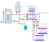
A hydraulic separator eliminates the need to use closely spaced tees when connecting load circuits. All load circuits can be piped across the headers. Those headers should be short, and generously sized. This keeps the pressure drop along the length of the header extremely small (e.g., negligible). The slow flow rate along the vertical height of the hydraulic separator adds virtually nothing to this pressure drop. Thus, the differential pressure between the upper and lower headers is essentially zero. Each load connected across the headers is unable to detect the presence of the other load circuits.Using closely spaced tees downstream of the hydraulic separator adds a second – and totally unnecessary – hydraulic separation between the lower circuits and the hydraulic separator itself. The lower circuits with the mixing valves will only receive heated water when those circuits connected across the header are active. At other times the water returning to the lower header will simply make a right-hand U-turn and be drawn back into the hot port of the mixing valve. The solution is simple: Just pipe all the loads across the headers as shown.
The expansion tank should also connect near the hydraulic separator as shown.
Finally, always put 10 or 12 pipe diameters of straight pipe on the inlet of any circulator to minimize turbulence into the impeller.


