The Glitch
The Glitch
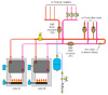
Overview: A few years ago, I toured a facility with a hydronic heating system laid out as shown at right. The systems supplied some air handlers using valves for zone control. It also supplied two other higher temperature loads using separate circuits with individual circulators. The system was supplied by two cast-iron atmospheric boilers.Exercise:Can you spot at least five details that need correcting?
The Fix
The Fix
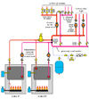
Let’s start with the heat source: The cardinal rule of multiple boiler systems is to only provide flow through a boiler that’s operating (and perhaps for a short post-purge period at the end of a firing cycle).There is no way the original system can do this.
The solution is to install a separate circulator and flow check on each boiler, and wire them to operate only when their associated boiler is providing heat to the system. In The Fix drawing, I’ve shown circulators with integral check valves mounted with the check valve under the circulator. This reduces the possibility of air being trapped in the circulator by the check valve. Ball valves are also provided to allow each boiler to be isolated if necessary.
Another error is the use of high head circulators with zone valves. This is never a good idea. It produces wide variations in differential pressure depending on which zones are operating. If a fixed speed circulator will be used with zone valves, it should have a flat pump curve. A differential pressure bypass valve should also be installed across the headers to help minimize variations in differential pressure.
Zone valves should be located on the supply side of the zone circuits to help prevent heat migration into inactive zone circuits.
Purging valves should be provided on all circuits.
The original distribution system is an “aberration” "


