Figure 1
The term “header” has been around the hydronics industry long before I got here. It refers to a piping assembly that divides an entering flow stream into two or more branches.
Sounds pretty simple, right? Just connect some tees together with short lengths of pipe to build a supply or return header that stretches out a few feet across the wall. Then connect a circulator to each branch.
Over the years I’ve come to realize that the “hydrodynamics” of headers significantly affects the operating characteristics of a hydronic system. With the right design, headers, along with other “common piping,” can provide very good hydraulic separation between simultaneously operating circulators. When done incorrectly, headers and common piping can set up a “circulator war” in which the big guys always manage to bully the little guys.
Perfect But Not Practical
The “ideal” hydronic supply header would split up entering flow into whatever number of branches it serves without causing any pressure variation between the supply connections. Likewise, the ideal return header would collect all return branch flows without causing any pressure variation between the return connections. To make this happen, the flow resistance within the header (e.g., between branch connections) must be zero.One concept that approaches this is a “spherical header.” Imagine a ball, made out of copper or steel, perhaps 10 or 12 inches in diameter, with several branch connections coming out of it in different directions (top, bottom, front, back, at angles, etc.). The flow velocity inside this ball would be very low, and thus the flow resistance across it (from one branch connection to the other) would also be extremely small - essentially zero. So there you have it, the perfect header, at least from the standpoint of hydrodynamics.
Too bad that manufacturing such a device would be so difficult and expensive. Too bad that installing such a device along a flat wall would be a pain. And too bad that making the piping connections to such a header look good would be darn near impossible! The perfect header, from the standpoint of hydrodynamics, is far from perfect when it comes to manufacturing and installation.
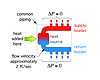
What to do? The next best thing is building a header that approximates the ideal conditions, but still allows for easy placement against a wall, and allows for organized and neat piping connections. Something such as shown in Figure 1.
The short length of this header and the closely spaced connections create very little pressure drop along the length of the header. My suggestion is to size the header such that the flow velocity on the supply end, with all branches operating at full design load flow, is about 2 feet per second. This will make the pressure drop along the header very low.
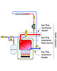
Figure 2
Common Piping
Take a look at Figure 2. It shows a supply and return header connected to a heat source that itself creates very little flow resistance. The flow path from the return header through the heat source, and back to the supply header, is called the “common piping” (e.g., flow from any branch circuit must pass through this piping as part of its circuit).If the flow resistance of the common piping and the headers is kept very low, the head energy added by each of the zone circulators is almost all dissipated as flow travels through the branch piping. Very little head energy is required to move flow through the common piping. When this is the case, it’s nearly impossible for individual circulators to “detect” the presence of other operating circulators within the system. This constitutes almost perfect hydraulic separation, and remains in effect even if there is a mixture of high-head, low-head or variable-speed circulators connected to the header system.

Figure 3a
Implications
Many of us have constructed primary/secondary piping systems. We’ve used closely spaced tees to approximate hydraulic separation between the primary loop and each secondary branch circuit.Primary/secondary piping works, but it’s not the only way to achieve hydraulic separation.
The schematic in Figure 3a is a classic parallel primary loop. The primary circulator must operate whenever any of the secondary circuits require heat. Flow splits up along the upper portion of the parallel primary loop, then passes down through each crossover. Balancing valves within each crossover are used to proportion flow to the percentage of the total load served by that crossover. The circulator supplied by the third crossover operates at variable speed to provide injection mixing to the low-temperature manifold station. A spring-loaded check, or thermal trap on the injection mixing piping, is required to prevent off-cycle heat migration.
The schematic in Figure 3b uses low-resistance headers and common piping, and the same low-resistance boiler to create hydraulic separation between the three circuits. No primary circulator, crossovers or balancing valves are necessary. Only one set of closely spaced tees, interfacing the injection risers to the low-temperature circuit.
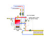
Figure 3b
Which of these systems would you rather build? Which of these do you think has the lower cost of materials and assembly labor? Which do you think has the lower electrical operating cost?
My guess is that your preference is Figure 3b. The foundation of its simplicity is the very low head loss along the headers and through the heat source.
Headers do indeed make quite a difference on the design of the system. Generously sized headers allow for simpler piping, lower installation cost and lower operating cost. Almost sounds like a “greener” approach, doesn’t it?
The next time you are planning headers for a hydronic system, remember: short/fat headers are good, long/skinny headers are bad.
