Two Certainties
Hydronic systems, like nature, want balance.
During 28 years of involvement with hydronic heating, I’ve had lots of opportunities to design and observe the operation of systems that worked great, as well as some that delivered a few surprises upon start-up. Like anyone who considers himself a professional, I’ve done the forensics on systems that didn’t operate as expected to avoid making the same mistakes twice. The corrections were then applied to future designs and incorporated in training programs that are supposed to represent best practices.
Over the years, these observations have confirmed certain behaviors that are common to all hydronic systems. When understood and respected, these traits always reveal why a given system does what it does. They can be a real asset both during design and troubleshooting.
Who’s In Charge? Fundamentally, there are two things that every hydronic system you’ll ever design or install “wants” to do:
Both conditions represent a balance between energy input and energy release.
Thermal equilibrium is the condition where the rate of heat input to the water from the heat source (boiler, heat pump, solar collector, etc.) is exactly the same as the rate of heat release from the water to the heat emitters. The supply water temperature and temperature drop the system stabilizes at are simply those necessary to balance these rates of heat flow. In some situations, these temperatures can be significantly higher or lower than what we expect depending on control settings.
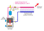
Here’s an example: Imagine a hydronic floor heating system containing eight parallel 350-ft. circuits of 1/2-inch PEX tubing embedded in a bare concrete slab. The system is directly piped to a 50,000 Btu/hr. boiler as shown in Figure 1. The boiler’s limit controller is set for 140 degrees F because that’s the supply temperature the installer thinks the system should operate.
When the system is fired up, the boiler temperature slowly climbs over a period of four hours and eventually stabilizes at 99 degrees F. Although the burner has been firing nonstop since it was first turned on, the installer thinks there’s something wrong. The boiler is not reaching the temperature he “told it to.” He grabs a wrench and whacks the limit controller a couple of times to show it who’s in charge.
After a few more hours, the boiler is still purring along at 99 degrees F outlet temperature, so he shuts off the system and pulls the limit controller from the boiler. Next stop - his local wholesaler, where he demands a replacement for the “obviously defective” limit controller.
This system is simply operating at thermal equilibrium, where heat input equals heat output. The floor heating system can release all 50,000 Btu/hr. of heat input without the supply water temperature having to rise above 99 degrees F. Because the limit controller is set well above this temperature, it cannot “intervene” and thus cannot affect the current operating conditions.
Incidentally, if the boiler supplying this system is not designed for continuous flue gas condensation, the installer will soon have more than the limit control to contend with. Thermal equilibrium doesn’t care if the boiler is condensing, it only cares that the heat flow rates are balanced.
Next, imagine the same installer creates a similar system with all the floor circuits shortened to a mere 40-ft. length. Having installed 2,800 ft. of PEX on the last job, he’s decided to save some money by installing minimal tubing and jack up the boiler temperature to 200 degrees F to compensate (trust me, these people are out there).
He turns on the system and watches the boiler supply temperature steadily climb to 200 degrees F, where the limit controller now complies with his wishes and turns off the burner. Unfortunately the building, which has a design heat load of 50,000 Btu/hr., still doesn’t maintain the desired 70 degree F indoor temperature during cold weather. This despite the fact the slab has cracked in several locations and a pair of seldom-worn rubber boots are now permanently fused to the floor.
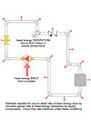
Aside from the fact that this installer is surely a contender for the next Darwin award, what’s going on? Well, if you simulate the performance of such a system assuming that all controls are disabled, you could calculate the supply temperature necessary for thermal equilibrium is about 251 degree F (see Figure 2). That’s where those skimpy floor circuits could actually dump the full 50,000 Btu/hr. of heat input into a 70 degree F room.
This condition could only occur if the safety controls stayed out of the picture, as in the first example. Since the limit controller won’t allow the supply water temperature to climb above 200 degree F, heat output is limited to about 35,800 Btu/hr. The same results would hold if a 1 million Btu/hr. boiler with a limit setting of 200 degrees F were used as the heat source.
 How many times have you been called to troubleshoot a system that doesn’t seem to be keeping the building warm and had someone on site tell you the boiler must be too small? It’s a natural conclusion, since the average Joe or Jane only understands that the building isn’t getting enough heat to stay comfortable and that the boiler is what “makes” heat for the building. It’s also almost never the cause of the problem. Instead, it’s far more likely the distribution system and/or heat emitters can’t deliver heat to the building at the rate the boiler can produce heat. As in the previous example, the system controls are not letting the system find its thermal equilibrium point. This is simply bad design rather than bad equipment.
You Can See It: Ever stand in a mechanical room and watch the temperature indicator on a boiler? Sometimes it slowly climbs as the boiler fires. What you’re seeing is the system trying to find thermal equilibrium. The fact that the temperature is increasing means that the boiler is currently injecting more heat into the system water than the distribution system is capable of releasing.
Many of you also have seen the opposite effect; a decrease in boiler temperature as the system operated. Perhaps it occurred when a cool slab with embedded tubing came online with a boiler that was already up to an elevated temperature. If the system did not have a mixing device that monitored boiler inlet temperature, you probably watched a rapid temperature descent to a condition where the boiler was only putting out lukewarm water even with its burner firing continuously.
 Once again, the system is simply seeking thermal equilibrium where heat output from the boiler matches heat absorption into the slab. Since the slab is cold, it’s absorbing heat from the circulating water much faster than the boiler can reproduce that heat by burning fuel. Hence, temperatures are headed downward until a balance is struck.
So, what can you conclude if you see the temperature indicator on a boiler holding steady even with the burner running nonstop? You got it - thermal equilibrium has been achieved.
Remember, every hydronic system always tries to operate at thermal equilibrium. It’s only the intervention of limiting controls that sometimes prevents this condition from occurring.
Flow Physics: There’s another form of energy constantly being put into and taken out of hydronic systems as they operate. It’s mechanical energy called head. An operating circulator converts electrical energy into head energy and imparts it to the fluid passing through the circulator. At the same time, every component through which this flow passes removes head energy due to friction. The system stabilizes at a flow rate where the rate of head energy input exactly matches the rate of head energy dissipation. This “hydraulic equilibrium” is usually achieved within a few seconds of turning on the circulator, and remains intact until the system operating condition is altered (i.e., a valve is adjusted, zone turned off or on, etc.). The concept is illustrated in Figure 3.
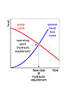 You can determine the hydraulic equilibrium point by finding the intersection of the system head loss curve and pump curve for the circulator (see Figure 4). The point where these curves cross is called the operating point and is the only possible condition where head input exactly balances head loss.
The system curve changes every time a zone circuit turns on or off as well as when someone adjusts a flow regulating valve. As soon as this takes place the system quickly settles to a new flow rate where head input from the circulator again matches head loss from the currently configured piping system. Think of the operating point sliding up or down the pump curve as necessary to maintain the balanced condition.
You’ve heard it said that nature likes a balance. This is perfectly illustrated through thermal and hydraulic equilibrium within all hydronic systems. Our task as designers is to also ensure the system delivers the desired comfort while it seeks to operate at both thermal and hydraulic equilibrium. When you ponder the operation of your systems from these stand-points, it all just makes sense.
Wishing you and your families a blessed Christmas.
Figure 1
During 28 years of involvement with hydronic heating, I’ve had lots of opportunities to design and observe the operation of systems that worked great, as well as some that delivered a few surprises upon start-up. Like anyone who considers himself a professional, I’ve done the forensics on systems that didn’t operate as expected to avoid making the same mistakes twice. The corrections were then applied to future designs and incorporated in training programs that are supposed to represent best practices.
Over the years, these observations have confirmed certain behaviors that are common to all hydronic systems. When understood and respected, these traits always reveal why a given system does what it does. They can be a real asset both during design and troubleshooting.
Who’s In Charge? Fundamentally, there are two things that every hydronic system you’ll ever design or install “wants” to do:
- Operate at thermal equilibrium
- Operate at hydraulic equilibrium
Both conditions represent a balance between energy input and energy release.
Thermal equilibrium is the condition where the rate of heat input to the water from the heat source (boiler, heat pump, solar collector, etc.) is exactly the same as the rate of heat release from the water to the heat emitters. The supply water temperature and temperature drop the system stabilizes at are simply those necessary to balance these rates of heat flow. In some situations, these temperatures can be significantly higher or lower than what we expect depending on control settings.
Here’s an example: Imagine a hydronic floor heating system containing eight parallel 350-ft. circuits of 1/2-inch PEX tubing embedded in a bare concrete slab. The system is directly piped to a 50,000 Btu/hr. boiler as shown in Figure 1. The boiler’s limit controller is set for 140 degrees F because that’s the supply temperature the installer thinks the system should operate.
When the system is fired up, the boiler temperature slowly climbs over a period of four hours and eventually stabilizes at 99 degrees F. Although the burner has been firing nonstop since it was first turned on, the installer thinks there’s something wrong. The boiler is not reaching the temperature he “told it to.” He grabs a wrench and whacks the limit controller a couple of times to show it who’s in charge.
After a few more hours, the boiler is still purring along at 99 degrees F outlet temperature, so he shuts off the system and pulls the limit controller from the boiler. Next stop - his local wholesaler, where he demands a replacement for the “obviously defective” limit controller.
This system is simply operating at thermal equilibrium, where heat input equals heat output. The floor heating system can release all 50,000 Btu/hr. of heat input without the supply water temperature having to rise above 99 degrees F. Because the limit controller is set well above this temperature, it cannot “intervene” and thus cannot affect the current operating conditions.
Incidentally, if the boiler supplying this system is not designed for continuous flue gas condensation, the installer will soon have more than the limit control to contend with. Thermal equilibrium doesn’t care if the boiler is condensing, it only cares that the heat flow rates are balanced.
Next, imagine the same installer creates a similar system with all the floor circuits shortened to a mere 40-ft. length. Having installed 2,800 ft. of PEX on the last job, he’s decided to save some money by installing minimal tubing and jack up the boiler temperature to 200 degrees F to compensate (trust me, these people are out there).
He turns on the system and watches the boiler supply temperature steadily climb to 200 degrees F, where the limit controller now complies with his wishes and turns off the burner. Unfortunately the building, which has a design heat load of 50,000 Btu/hr., still doesn’t maintain the desired 70 degree F indoor temperature during cold weather. This despite the fact the slab has cracked in several locations and a pair of seldom-worn rubber boots are now permanently fused to the floor.
Aside from the fact that this installer is surely a contender for the next Darwin award, what’s going on? Well, if you simulate the performance of such a system assuming that all controls are disabled, you could calculate the supply temperature necessary for thermal equilibrium is about 251 degree F (see Figure 2). That’s where those skimpy floor circuits could actually dump the full 50,000 Btu/hr. of heat input into a 70 degree F room.
This condition could only occur if the safety controls stayed out of the picture, as in the first example. Since the limit controller won’t allow the supply water temperature to climb above 200 degree F, heat output is limited to about 35,800 Btu/hr. The same results would hold if a 1 million Btu/hr. boiler with a limit setting of 200 degrees F were used as the heat source.
Figure 2
You Can See It: Ever stand in a mechanical room and watch the temperature indicator on a boiler? Sometimes it slowly climbs as the boiler fires. What you’re seeing is the system trying to find thermal equilibrium. The fact that the temperature is increasing means that the boiler is currently injecting more heat into the system water than the distribution system is capable of releasing.
Many of you also have seen the opposite effect; a decrease in boiler temperature as the system operated. Perhaps it occurred when a cool slab with embedded tubing came online with a boiler that was already up to an elevated temperature. If the system did not have a mixing device that monitored boiler inlet temperature, you probably watched a rapid temperature descent to a condition where the boiler was only putting out lukewarm water even with its burner firing continuously.
Figure 3
So, what can you conclude if you see the temperature indicator on a boiler holding steady even with the burner running nonstop? You got it - thermal equilibrium has been achieved.
Remember, every hydronic system always tries to operate at thermal equilibrium. It’s only the intervention of limiting controls that sometimes prevents this condition from occurring.
Flow Physics: There’s another form of energy constantly being put into and taken out of hydronic systems as they operate. It’s mechanical energy called head. An operating circulator converts electrical energy into head energy and imparts it to the fluid passing through the circulator. At the same time, every component through which this flow passes removes head energy due to friction. The system stabilizes at a flow rate where the rate of head energy input exactly matches the rate of head energy dissipation. This “hydraulic equilibrium” is usually achieved within a few seconds of turning on the circulator, and remains intact until the system operating condition is altered (i.e., a valve is adjusted, zone turned off or on, etc.). The concept is illustrated in Figure 3.
Figure 4
The system curve changes every time a zone circuit turns on or off as well as when someone adjusts a flow regulating valve. As soon as this takes place the system quickly settles to a new flow rate where head input from the circulator again matches head loss from the currently configured piping system. Think of the operating point sliding up or down the pump curve as necessary to maintain the balanced condition.
You’ve heard it said that nature likes a balance. This is perfectly illustrated through thermal and hydraulic equilibrium within all hydronic systems. Our task as designers is to also ensure the system delivers the desired comfort while it seeks to operate at both thermal and hydraulic equilibrium. When you ponder the operation of your systems from these stand-points, it all just makes sense.
Wishing you and your families a blessed Christmas.
Looking for a reprint of this article?
From high-res PDFs to custom plaques, order your copy today!