Once upon a time...
A schematic appeared in a manufacturer’s installation manual. It was their recommended way to install a two-zone system using zone valves.
The Glitch
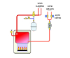
A schematic very similar to that shown below appeared in a manufacturer’s installation manual. It was their recommended way to install a two-zone system using zone valves.
Can you identify at least five things that should be changed to improve this system?

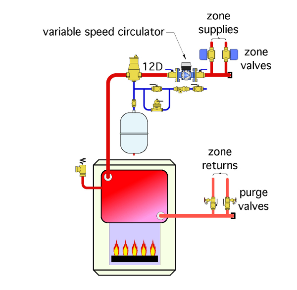
The Fix
What’s wrong?
1. The zone valves should be located on the supply side of the zone circuits to eliminate heat migration into inactive zone circuits.
2. The tee shown below the zone valves is a bullhead tee. When both zones are on, return flows slam directly into each other. This creates turbulence and noise. It also wastes circulator head.
3. There should be at least 12 diameters of straight pipe leading into the circulator. Placing it close to the side port of the bullhead tee allows turbulent flow into the circulator. This decreases circulator performance and creates noise.
4. The circulator in the Glitch drawing is pumping toward rather than away from the expansion tank. This causes a decrease in pressure within the zone circuits when their circulators operate.
5. There is no provision for differential pressure control in the original system. If you are going to use a fixed-speed circulator, make sure it has a flat pump curve and install a differential-pressure bypass valve.
An even better solution, shown in the Fix drawing, is to install a variable-speed circulator that reduces circulator speed when only one zone valve is open. They are now available in the United States from at least four manufacturers. Why not reduce wattage when only one zone is operating?
6. There are no purging valves in the original system.
7. A backflow preventer and fast-fill bypass ball valve have been added to the make-up water assembly.
Links
Looking for a reprint of this article?
From high-res PDFs to custom plaques, order your copy today!


