Pavement To Pool
A possible operating
mode for some hydronic systems.

Those of you old enough to remember the “Jimmy Durante Show” might remember one of his famous lines. After cracking a joke, Jimmy would add the kicker: “I got a million of ’em, a million of ’em.”
While I can’t claim to have Durante’s stash of jokes, I do have quite a stash of schematics for hydronic heating systems. Probably not a million, but more than enough to eventually bore even the more ardent hydronics aficionados.
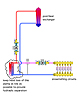
One of the more recent creations comes from the third edition of my textbook “Modern Hydronic Heating.” It’s shown in Figure 1.
This schematic shows a subsystem for supplying two loads that are often used in higher-end hydronic systems: snow melting and pool heating.
The snow-melting system uses a three-way motorized mixing valve to control the supply temperature to the embedded tubing. This portion of the system operates with a 40 to 50 percent solution of propylene glycol antifreeze.
The pool heat exchanger is assumed to be located outside - perhaps near the pool - and thus subject to freezing in winter. The pool water side would be drained at the end of each swimming season, but the heat input side would remain filled with the antifreeze solution.
The strap-on aquastat seen below the plate heat exchanger verifies that heated water is flowing through the hot side of the exchanger before allowing operation of either circulator on the antifreeze side of the exchanger. This protects the heat exchanger from freezing during very cold startups of the snow-melting system, especially during the time when the boiler is just warming up.
This brings us back to Figure 1. Although the original intent of this piping arrangement is to deliver heat to either the pool or the snow-melting circuits, there is a synergy that lends itself to another possible use: moving heat from hot pavement to a cooler swimming pool.
To make this happen, the circulator for the snow-melting subsystem, the circulator supplying the swimming pool heat exchanger and the pool filter pump have to be operating. The three-way mixing valve within the snow-melting subsystem should be fully open so there is no flow in the bypass pipe. Finally, the circulator on the left side of the plate heat exchanger that would normally deliver heat to the exchanger needs to be off.
Given these conditions, the two circuits are essentially stirring an antifreeze solution between them. If that fluid passes through tubing embedded in pavement that’s warmer than the fluid, it will absorb heat. When the warmed fluid subsequently passes through the pool heat exchanger, it will give off heat - assuming the pool water enters the other side of the heat exchanger at a lower temperature.
The flow rates produced in each portion of the system would depend on the piping sizes, lengths, flow resistance of the pool heat exchanger and what circulators are used in each branch. This could all be calculated for a specific arrangement of known components.
When my wife and I installed a swimming pool back in 1992, I couldn’t resist adding some 5/8-inch PEX tubing in the concrete walkway around the pool’s perimeter. I tied the PEX circuits to a standard manifold and piped it into the pool filter pump piping so that some pool water would be forced through the PEX circuits whenever the pool filter pump was operating.
Although I’ve never instrumented my installation, I can tell you the embedded tubing does gather up heat from the bare concrete pavement around the pool on a sunny summer day. You can feel the higher-temperature water coming back into the pool water inlets.
After watching this little experiment work for a few years, I observed the following:
An asphalt driveway surface gets
substantially warmer than a bare concrete surface under the same solar
radiation conditions. That’s because the absorptivity of bare concrete (about
0.60) is lower than that of asphalt (about 0.95). If you’re serious about
absorbing heat from a solar-radiated pavement, it should be as dark as possible
and in a location receiving good solar gain most of the day.
If you plan to use this concept with an asphalt driveway, the color is pretty much a given and favorable for solar heat absorption. If you plan to try this under concrete, you really need to consider staining that concrete to increase absorption of solar radiation. While flat black is ideal, it may be a hard sell based on aesthetics. Darker shades of green, gray or brown would likely yield reasonably good absorptivity.
There is a significant time delay
between when the pavement surface reaches its maximum temperature (based on air
temperature and solar radiation) and when the water returning from the embedded
tubing delivers its warmest water to the pool. This is not surprising. There’s
a lot of thermal mass between the pavement surface and the layer of embedded
tubing.
This mass is often cooled by radiation to a clear nighttime sky, and thus needs to be rewarmed by the sun the following day before heat makes it back down to the tubing. If the pavement-to-pool operating mode starts too early in the day, the result may be undesired heat transfer from the pool to the pavement.
1. A pavement temperature sensor needs to be located in a well that’s buried in the pavement at the same depth as the tubing. This sensor should be removable. The sensor well should be located within pavement that receives solar radiation whenever it’s available (e.g., not in a shaded or partially shaded location).
2. A differential temperature controller, the same as used to control solar DHW systems, would be a good choice to supervise this mode of operation. One sensor would be located in the pavement sensor well, the other so that it senses the temperature of water returning from the pool to the filter. The latter sensor also should be in a well that’s immersed in the passing water stream. It should not be strapped on the outside of a PVC pipe due to the higher thermal resistance of the pipe wall.
When the temperature sensor located in the pavement is perhaps 2 degrees F or more higher than the temperature of water coming back from the pool, the circulators and the mixing valve would operate to transfer heat from the pavement to the pool. When this difference drops to 1 degree F, this mode of operation would be stopped. The latter might occur at some late evening or early morning hour, depending on the previous day’s weather and the degree of night cooling experienced by the pavement.
3. The depth of the tubing within the pavement definitely affects performance. Keeping the tubing within a couple inches of the surface would seem to be ideal if possible. Of course, this has to be weighed against control joint depths and the practicality of placing concrete or asphalt pavement with relatively shallow embedded tubing.
4. Keep the head loss across the plate heat exchanger and “common piping” shared by each branch circuit as low as possible (see Figure 2). Low head loss at this location provides reasonably good hydraulic separation and minimizes flow rate variations when the circulators operate simultaneously (pavement-to-pool mode) vs. when they operate individually (during individual calls for snow melting or boiler-to-pool heating).
5. Generously size the pool heat exchanger. The greater the internal surface area of this heat exchanger, the greater the rate of heat transfer. This is especially important given the relatively small temperature differential between the entering warm antifreeze and entering pool water. An undersized pool heat exchanger is a bottleneck on the entire heat transfer process. The size of the plate heat exchanger does not have to be altered based on heat transfer.
6. The coolest water is typically at the bottom of the pool. Setting up the pool piping so that water is drawn from the pool’s bottom drain, passed through the filter and then through the heat exchanger will maximize energy transfer during the pavement-to-pool mode.
7. If the pavement-to-pool operation is not achieving the desired pool temperature, the heat plant will likely be called upon to add heat in the normal manner. Be sure your control strategy recognizes this and turns off the snow-melting circulator to prevent energy transfer to the pavement. It’s pretty hard to explain why a boiler should be operating on a hot summer day to add heat to a driveway ...
Beyond what’s been discussed, I really have no specific formulas or graphs to fine-tune this strategy. At least not yet. It’s likely this operating mode would be employed only in limited situations where both snow melting and pool heating are planned, and where a suitable sun-drenched dark pavement is also present. Still, this unique operating mode is another example of the versatility of hydronics technology that, in the right situation, can add significant value at very little additional cost.
Figure 1
Those of you old enough to remember the “Jimmy Durante Show” might remember one of his famous lines. After cracking a joke, Jimmy would add the kicker: “I got a million of ’em, a million of ’em.”
While I can’t claim to have Durante’s stash of jokes, I do have quite a stash of schematics for hydronic heating systems. Probably not a million, but more than enough to eventually bore even the more ardent hydronics aficionados.
One of the more recent creations comes from the third edition of my textbook “Modern Hydronic Heating.” It’s shown in Figure 1.
This schematic shows a subsystem for supplying two loads that are often used in higher-end hydronic systems: snow melting and pool heating.
The snow-melting system uses a three-way motorized mixing valve to control the supply temperature to the embedded tubing. This portion of the system operates with a 40 to 50 percent solution of propylene glycol antifreeze.
The pool heat exchanger is assumed to be located outside - perhaps near the pool - and thus subject to freezing in winter. The pool water side would be drained at the end of each swimming season, but the heat input side would remain filled with the antifreeze solution.
The strap-on aquastat seen below the plate heat exchanger verifies that heated water is flowing through the hot side of the exchanger before allowing operation of either circulator on the antifreeze side of the exchanger. This protects the heat exchanger from freezing during very cold startups of the snow-melting system, especially during the time when the boiler is just warming up.
One Source, Many Loads
I’ve long promoted the concept of multiload hydronic systems in which a single “heat plant” (such as a multiboiler system) supplies all thermally based loads in and around a building. These include space heating, domestic water heating, garage heating, snow melting and pool heating. There are several advantages to such an approach:- 1. It consolidates all fuel supply
and venting to one location in the building.
2. It reduces the maintenance associated with having separate heat sources for each load.
3. It improves boiler efficiency by helping to level the load profile against which the heat plant is operating. Strategies such as prioritized domestic water heating and staged “load shedding” allow all the loads to be met under just about any reasonable operating strategy without having significantly oversized heat sources. Load leveling also helps keep the “appointment book” for the heat plant well-filled. This keeps the efficiency of nonmodulating boilers closer to desirable steady-state conditions.
4. It allows a multiple boiler system to deliver a high rate of heat output when necessary, such as when there is a large demand for domestic hot water, yet still retain good capacity control and efficiency under the much more common partial-load conditions.
Swimming Pool Heated By Driveway?
One question I’ve been asked many times could be paraphrased as follows: Is it possible to use heat from a driveway, on a sunny summer day, to heat a swimming pool? The simple answer is yes, but the required mechanics and performance expectations are not as easily answered.This brings us back to Figure 1. Although the original intent of this piping arrangement is to deliver heat to either the pool or the snow-melting circuits, there is a synergy that lends itself to another possible use: moving heat from hot pavement to a cooler swimming pool.
To make this happen, the circulator for the snow-melting subsystem, the circulator supplying the swimming pool heat exchanger and the pool filter pump have to be operating. The three-way mixing valve within the snow-melting subsystem should be fully open so there is no flow in the bypass pipe. Finally, the circulator on the left side of the plate heat exchanger that would normally deliver heat to the exchanger needs to be off.
Given these conditions, the two circuits are essentially stirring an antifreeze solution between them. If that fluid passes through tubing embedded in pavement that’s warmer than the fluid, it will absorb heat. When the warmed fluid subsequently passes through the pool heat exchanger, it will give off heat - assuming the pool water enters the other side of the heat exchanger at a lower temperature.
The flow rates produced in each portion of the system would depend on the piping sizes, lengths, flow resistance of the pool heat exchanger and what circulators are used in each branch. This could all be calculated for a specific arrangement of known components.
When my wife and I installed a swimming pool back in 1992, I couldn’t resist adding some 5/8-inch PEX tubing in the concrete walkway around the pool’s perimeter. I tied the PEX circuits to a standard manifold and piped it into the pool filter pump piping so that some pool water would be forced through the PEX circuits whenever the pool filter pump was operating.
Although I’ve never instrumented my installation, I can tell you the embedded tubing does gather up heat from the bare concrete pavement around the pool on a sunny summer day. You can feel the higher-temperature water coming back into the pool water inlets.
After watching this little experiment work for a few years, I observed the following:
If you plan to use this concept with an asphalt driveway, the color is pretty much a given and favorable for solar heat absorption. If you plan to try this under concrete, you really need to consider staining that concrete to increase absorption of solar radiation. While flat black is ideal, it may be a hard sell based on aesthetics. Darker shades of green, gray or brown would likely yield reasonably good absorptivity.
This mass is often cooled by radiation to a clear nighttime sky, and thus needs to be rewarmed by the sun the following day before heat makes it back down to the tubing. If the pavement-to-pool operating mode starts too early in the day, the result may be undesired heat transfer from the pool to the pavement.
Figure 2
Pavement-To-Pool Heating Tips
Based on these observations and good hydronic design practice, I offer these seven suggestions to those interested in pursuing this concept:1. A pavement temperature sensor needs to be located in a well that’s buried in the pavement at the same depth as the tubing. This sensor should be removable. The sensor well should be located within pavement that receives solar radiation whenever it’s available (e.g., not in a shaded or partially shaded location).
2. A differential temperature controller, the same as used to control solar DHW systems, would be a good choice to supervise this mode of operation. One sensor would be located in the pavement sensor well, the other so that it senses the temperature of water returning from the pool to the filter. The latter sensor also should be in a well that’s immersed in the passing water stream. It should not be strapped on the outside of a PVC pipe due to the higher thermal resistance of the pipe wall.
When the temperature sensor located in the pavement is perhaps 2 degrees F or more higher than the temperature of water coming back from the pool, the circulators and the mixing valve would operate to transfer heat from the pavement to the pool. When this difference drops to 1 degree F, this mode of operation would be stopped. The latter might occur at some late evening or early morning hour, depending on the previous day’s weather and the degree of night cooling experienced by the pavement.
3. The depth of the tubing within the pavement definitely affects performance. Keeping the tubing within a couple inches of the surface would seem to be ideal if possible. Of course, this has to be weighed against control joint depths and the practicality of placing concrete or asphalt pavement with relatively shallow embedded tubing.
4. Keep the head loss across the plate heat exchanger and “common piping” shared by each branch circuit as low as possible (see Figure 2). Low head loss at this location provides reasonably good hydraulic separation and minimizes flow rate variations when the circulators operate simultaneously (pavement-to-pool mode) vs. when they operate individually (during individual calls for snow melting or boiler-to-pool heating).
5. Generously size the pool heat exchanger. The greater the internal surface area of this heat exchanger, the greater the rate of heat transfer. This is especially important given the relatively small temperature differential between the entering warm antifreeze and entering pool water. An undersized pool heat exchanger is a bottleneck on the entire heat transfer process. The size of the plate heat exchanger does not have to be altered based on heat transfer.
6. The coolest water is typically at the bottom of the pool. Setting up the pool piping so that water is drawn from the pool’s bottom drain, passed through the filter and then through the heat exchanger will maximize energy transfer during the pavement-to-pool mode.
7. If the pavement-to-pool operation is not achieving the desired pool temperature, the heat plant will likely be called upon to add heat in the normal manner. Be sure your control strategy recognizes this and turns off the snow-melting circulator to prevent energy transfer to the pavement. It’s pretty hard to explain why a boiler should be operating on a hot summer day to add heat to a driveway ...
Beyond what’s been discussed, I really have no specific formulas or graphs to fine-tune this strategy. At least not yet. It’s likely this operating mode would be employed only in limited situations where both snow melting and pool heating are planned, and where a suitable sun-drenched dark pavement is also present. Still, this unique operating mode is another example of the versatility of hydronics technology that, in the right situation, can add significant value at very little additional cost.
Links
Looking for a reprint of this article?
From high-res PDFs to custom plaques, order your copy today!