From Wood To Water, Part 1
Interfacing wood gasification boilers with modern
hydronics.

Every August, a village not far from where I live hosts an event called the “Woodsmen’s Field Days.” It’s one of the largest gatherings of its kind in the country, and demonstrates state-of-the-art ways to cut down trees and then turn them into lumber, firewood, chips or shavings. If you like 75-horsepower souped-up chainsaws, razor-sharp blades, diesel engines, hydraulic power and big pickups, this is the show for you.
While there, you might want to cut a deal on a machine that lets you load 16-foot logs on one end and drive away from the other end in a dump truck full of split cord wood. The only things you touch to make this happen are a few hydraulic control levers.
If you’re burning about 50 face cords of firewood every winter - like one of my neighbors does - this rig could probably pay for itself before you die, or cut down the last tree on your property.
Being a bit less ambitious with my chainsaw, I’d rather approach the situation from the other direction: reduce the load, burn the wood as efficiently as possible and accurately control those Btu once you’ve created them. Toward that end, this is the first in a series of columns on interfacing high-efficiency, wood-gasification boilers with state-of-the-art hydronics.
Creosote left unattended is a disaster waiting to happen. Because it’s formed from unburned hydrocarbons, creosote has considerable fuel value. If sufficiently reheated by other combustion products, or flames, that fuel value can quickly reappear in the form of a chimney fire.
One of the best ways to minimize creosote formation and boost efficiency is to burn firewood as hot as possible. Some wood-fired boilers are now designed to do this using a combustion air blower and ceramic combustion chamber. These so-called wood-gasification boilers create combustion zone temperatures over 2,000 degrees F and corresponding efficiencies currently in the high 80s (and even into the 90s in the not-too-distant future). This form of combustion leaves very little residue. Much less than is typical with a wood stove.
The hot pyrolytic gases created in the primary combustion chamber of a wood-gasification boiler are pushed downward through a specially shaped ceramic orifice by pressurized air from a blower. Additional air is injected into this gas stream at the orifice. The result is a blow-torch-like flame as seen in Figure 1. (If you want to see this in action, visit YouTube.com and search for “Econoburn gasification.”)
Most wood-gasification boilers have variable-speed combustion air blowers that can partially throttle the combustion process when the water in the boiler reaches a set high-temperature limit. However, the highest overall combustion efficiency is achieved when a full load of wood is burned at the maximum combustion rate possible, as determined by the blower’s capacity. This results in a “burst” of heat output that lasts as long as it takes to burn off a firebox full of wood (usually two to four hours).
During this time, the heating or domestic hot water load in the building may be small or nonexistent. The mismatch between instantaneous heat output and heating load is a common characteristic of wood-fired heating systems. The mismatch is further exacerbated by zoning, which is a benefit we don’t forego just because we’re heating with wood.
The solution is to add thermal mass in the form of a buffer between the boiler and load. This tank absorbs any heat output in excess of the current load. When necessary, it also releases heat to the load at rates that can be far greater than the current output from the boiler. In short, a buffer tank “stabilizes” what would otherwise be a difficult process to control.
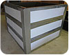
An unpressurized buffer tank is essentially an insulated cistern with a cover. There is a vent at the top of the tank; thus, the water it contains is not isolated from the atmosphere. An example of a partially assembled, unpressurized buffer tank is shown in Figure 2.
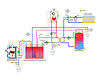
A schematic for a system using such a tank along with a gas-fired auxiliary boiler is shown in Figure 3.
Unpressurized buffer tanks typically have two or three suspended copper heat exchanger coils. Each coil is part of a separate pressurized circuit. One delivers heat from the boiler to the tank. Another extracts heat for space heating. If the system provides domestic water heating, a third coil is installed in the tank.
This configuration retains the advantages of closed hydronic circuits (e.g., low potential for corrosion, quiet circulator operation, minimal make-up water and less potential for cavitation). Furthermore, unpressurized tanks typically cost less (per gallon) than do pressure-rated tanks. Several models are designed for on-site assembly, which reduces transportation and rigging costs.
Another advantage is that the expansion tank(s) in the closed hydronic circuits need only accommodate the fluid expansion in those circuits, and not that of the water in the buffer tank. The latter is handled by maintaining the water level in the buffer tank a few inches below the top of the sidewalls.
The downside to an open tank is that evaporation losses occur over time. It is necessary for someone to periodically check tank water level and add make-up water to keep all coils fully submerged.
We’ll look at one control option that assumes all heat from the wood-fired boiler is dumped into a buffer tank (as would be true for the system shown in Figure 3). The buffer tank then serves as the “priority” heat source for both space heating and domestic water heating. The auxiliary boiler operates only when heat from the buffer tank cannot produce the necessary supply temperatures for these loads.
One additional constraint that simplifies control requirements is that heat from the wood-fired boiler is only added to domestic water as that water passes through the suspended coil in the buffer tank. In other words, the buffer tank can not serve as a heat source for the coil of the indirect water heater. However, the auxiliary boiler can still boost domestic water temperature within the indirect tank when necessary.
With this constraint in mind, here is a description of the control operation for the system shown in Figure 3.
1. The blower on the wood-gasification boiler modulates speed based on the boiler’s temperature controller. If the water in the boiler approaches the limit setting, blower speed is reduced. The circulator (P1) operates whenever the boiler is in use. As the boiler is heating up, most of the water leaving it is shunted back to its inlet by the three-way thermostatic valve. This temporarily “uncouples” the boiler from the tank coil so its temperature can rise above the point where creosote would form on the firebox walls.
When the boiler inlet temperature reaches a suitable value (typically around 140 degrees F), the thermostatic valve smoothly redirects hot water flow to the buffer tank’s heat input coil. It’s the same anti-condensation concept we’ve discussed for conventional boilers in many past columns.
2. Upon a call for space heating, the motorized three-way mixing valve controller (C2) turns on the distribution circulator (P5) and calculates the necessary supply temperature to the radiant panel circuits. This controller calls for heat input by closing a set of contacts to power up the outdoor reset controller (C1), which monitors water temperature at the top of the buffer tank.
If this temperature is at or above the calculated target temperature minus half the control differential, the relay adjacent to the controller (C1) turns on the buffer tank circulator (P2), allowing the tank to supply heat to the space-heating load. If the tank is below this target temperature minus half the control differential, the relay turns on the auxiliary boiler and its circulator (P3). When operating, the auxiliary boiler’s internal reset controller regulates boiler discharge temperature.
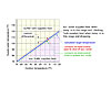
A graph depicting the reset control function provided by controller (C1) is shown in Figure 4.
3. Domestic water heating is treated as a priority load. When the aquastat on the indirect water heater calls for heat, the buffer tank circulator (P2), if it’s currently running, is turned off. Circulator (P4) is turned on, as is the auxiliary boiler and circulator (P3). The discharge temperature from the auxiliary boiler is regulated based on its setting for the domestic water-heating mode.
Keep in mind that all domestic water that enters the indirect heater must first pass through the suspended coil in the buffer tank. If the water in the buffer tank is relatively warm, say 120 degrees F, and the suspended coil is generously sized, most of the domestic water-heating temperature rise takes place as the water passes through this coil.
The only limitation of this approach is that wood-sourced energy cannot “top off” the water temperature in the indirect tank, assuming that the temperature of the buffer tank was high enough to do so. I don’t see this as a significant negative, especially given the relative simplicity of the control method it allows.
Another consideration is that, under load, water leaving the buffer tank’s space-heating coil will be at a slightly lower temperature than the water at the top of the buffer tank. How much lower depends on the size of the coil relative to the load. Larger coils and lower loads will minimize this difference. One could compensate for this by setting the outdoor reset controller (C1) for a slightly steeper reset line.
This system produces a seamless transition between heat derived from the wood-gasification boiler and that produced by the auxiliary boiler. Building occupants would feel no difference in comfort regardless of which heat source is currently active. It allows one to configure a fully zoned distribution system using the latest variable-speed circulator technology. It even allows additional options such as heat input from a solar collector array. We’ll look at this, as well as pressurized buffer tanks, in December.
Figure 1 Photo courtesy of Dunkirk Metal Products
Every August, a village not far from where I live hosts an event called the “Woodsmen’s Field Days.” It’s one of the largest gatherings of its kind in the country, and demonstrates state-of-the-art ways to cut down trees and then turn them into lumber, firewood, chips or shavings. If you like 75-horsepower souped-up chainsaws, razor-sharp blades, diesel engines, hydraulic power and big pickups, this is the show for you.
While there, you might want to cut a deal on a machine that lets you load 16-foot logs on one end and drive away from the other end in a dump truck full of split cord wood. The only things you touch to make this happen are a few hydraulic control levers.
If you’re burning about 50 face cords of firewood every winter - like one of my neighbors does - this rig could probably pay for itself before you die, or cut down the last tree on your property.
Being a bit less ambitious with my chainsaw, I’d rather approach the situation from the other direction: reduce the load, burn the wood as efficiently as possible and accurately control those Btu once you’ve created them. Toward that end, this is the first in a series of columns on interfacing high-efficiency, wood-gasification boilers with state-of-the-art hydronics.
Figure 2 Photo courtesy of American Solartechnics
Hot And Fast
One fundamental fact of wood burning is that high combustion temperature equals high efficiency. When wood is sufficiently heated, it gives off pyrolytic gases. Given high enough temperatures and the presence of oxygen, these gases combust to liberate heat. However, if the temperature in the combustion chamber is too low or the combustion zone is starved for oxygen, a significant portion of the pyrolytic gases will not combust. Instead, they pass into the chimney, cool and condense as creosote - a sticky, tar-like substance that eventually hardens in layers against the chimney walls.Creosote left unattended is a disaster waiting to happen. Because it’s formed from unburned hydrocarbons, creosote has considerable fuel value. If sufficiently reheated by other combustion products, or flames, that fuel value can quickly reappear in the form of a chimney fire.
One of the best ways to minimize creosote formation and boost efficiency is to burn firewood as hot as possible. Some wood-fired boilers are now designed to do this using a combustion air blower and ceramic combustion chamber. These so-called wood-gasification boilers create combustion zone temperatures over 2,000 degrees F and corresponding efficiencies currently in the high 80s (and even into the 90s in the not-too-distant future). This form of combustion leaves very little residue. Much less than is typical with a wood stove.
The hot pyrolytic gases created in the primary combustion chamber of a wood-gasification boiler are pushed downward through a specially shaped ceramic orifice by pressurized air from a blower. Additional air is injected into this gas stream at the orifice. The result is a blow-torch-like flame as seen in Figure 1. (If you want to see this in action, visit YouTube.com and search for “Econoburn gasification.”)
Most wood-gasification boilers have variable-speed combustion air blowers that can partially throttle the combustion process when the water in the boiler reaches a set high-temperature limit. However, the highest overall combustion efficiency is achieved when a full load of wood is burned at the maximum combustion rate possible, as determined by the blower’s capacity. This results in a “burst” of heat output that lasts as long as it takes to burn off a firebox full of wood (usually two to four hours).
During this time, the heating or domestic hot water load in the building may be small or nonexistent. The mismatch between instantaneous heat output and heating load is a common characteristic of wood-fired heating systems. The mismatch is further exacerbated by zoning, which is a benefit we don’t forego just because we’re heating with wood.
The solution is to add thermal mass in the form of a buffer between the boiler and load. This tank absorbs any heat output in excess of the current load. When necessary, it also releases heat to the load at rates that can be far greater than the current output from the boiler. In short, a buffer tank “stabilizes” what would otherwise be a difficult process to control.
Figure 3
Open And Shut Cases
Buffer tanks can be either pressurized or unpressurized. Both have their benefits and limitations. This month we’ll focus on unpressurized tanks. In part two, we’ll take a look at pressurized vessels.An unpressurized buffer tank is essentially an insulated cistern with a cover. There is a vent at the top of the tank; thus, the water it contains is not isolated from the atmosphere. An example of a partially assembled, unpressurized buffer tank is shown in Figure 2.
A schematic for a system using such a tank along with a gas-fired auxiliary boiler is shown in Figure 3.
Unpressurized buffer tanks typically have two or three suspended copper heat exchanger coils. Each coil is part of a separate pressurized circuit. One delivers heat from the boiler to the tank. Another extracts heat for space heating. If the system provides domestic water heating, a third coil is installed in the tank.
This configuration retains the advantages of closed hydronic circuits (e.g., low potential for corrosion, quiet circulator operation, minimal make-up water and less potential for cavitation). Furthermore, unpressurized tanks typically cost less (per gallon) than do pressure-rated tanks. Several models are designed for on-site assembly, which reduces transportation and rigging costs.
Another advantage is that the expansion tank(s) in the closed hydronic circuits need only accommodate the fluid expansion in those circuits, and not that of the water in the buffer tank. The latter is handled by maintaining the water level in the buffer tank a few inches below the top of the sidewalls.
The downside to an open tank is that evaporation losses occur over time. It is necessary for someone to periodically check tank water level and add make-up water to keep all coils fully submerged.
Figure 4
Under Control
The controls used for systems with wood-fired boilers vary considerably, depending on how the system is intended to operate, the presence or lack of a buffer tank and the loads being served.We’ll look at one control option that assumes all heat from the wood-fired boiler is dumped into a buffer tank (as would be true for the system shown in Figure 3). The buffer tank then serves as the “priority” heat source for both space heating and domestic water heating. The auxiliary boiler operates only when heat from the buffer tank cannot produce the necessary supply temperatures for these loads.
One additional constraint that simplifies control requirements is that heat from the wood-fired boiler is only added to domestic water as that water passes through the suspended coil in the buffer tank. In other words, the buffer tank can not serve as a heat source for the coil of the indirect water heater. However, the auxiliary boiler can still boost domestic water temperature within the indirect tank when necessary.
With this constraint in mind, here is a description of the control operation for the system shown in Figure 3.
1. The blower on the wood-gasification boiler modulates speed based on the boiler’s temperature controller. If the water in the boiler approaches the limit setting, blower speed is reduced. The circulator (P1) operates whenever the boiler is in use. As the boiler is heating up, most of the water leaving it is shunted back to its inlet by the three-way thermostatic valve. This temporarily “uncouples” the boiler from the tank coil so its temperature can rise above the point where creosote would form on the firebox walls.
When the boiler inlet temperature reaches a suitable value (typically around 140 degrees F), the thermostatic valve smoothly redirects hot water flow to the buffer tank’s heat input coil. It’s the same anti-condensation concept we’ve discussed for conventional boilers in many past columns.
2. Upon a call for space heating, the motorized three-way mixing valve controller (C2) turns on the distribution circulator (P5) and calculates the necessary supply temperature to the radiant panel circuits. This controller calls for heat input by closing a set of contacts to power up the outdoor reset controller (C1), which monitors water temperature at the top of the buffer tank.
If this temperature is at or above the calculated target temperature minus half the control differential, the relay adjacent to the controller (C1) turns on the buffer tank circulator (P2), allowing the tank to supply heat to the space-heating load. If the tank is below this target temperature minus half the control differential, the relay turns on the auxiliary boiler and its circulator (P3). When operating, the auxiliary boiler’s internal reset controller regulates boiler discharge temperature.
A graph depicting the reset control function provided by controller (C1) is shown in Figure 4.
3. Domestic water heating is treated as a priority load. When the aquastat on the indirect water heater calls for heat, the buffer tank circulator (P2), if it’s currently running, is turned off. Circulator (P4) is turned on, as is the auxiliary boiler and circulator (P3). The discharge temperature from the auxiliary boiler is regulated based on its setting for the domestic water-heating mode.
Keep in mind that all domestic water that enters the indirect heater must first pass through the suspended coil in the buffer tank. If the water in the buffer tank is relatively warm, say 120 degrees F, and the suspended coil is generously sized, most of the domestic water-heating temperature rise takes place as the water passes through this coil.
The only limitation of this approach is that wood-sourced energy cannot “top off” the water temperature in the indirect tank, assuming that the temperature of the buffer tank was high enough to do so. I don’t see this as a significant negative, especially given the relative simplicity of the control method it allows.
Another consideration is that, under load, water leaving the buffer tank’s space-heating coil will be at a slightly lower temperature than the water at the top of the buffer tank. How much lower depends on the size of the coil relative to the load. Larger coils and lower loads will minimize this difference. One could compensate for this by setting the outdoor reset controller (C1) for a slightly steeper reset line.
This system produces a seamless transition between heat derived from the wood-gasification boiler and that produced by the auxiliary boiler. Building occupants would feel no difference in comfort regardless of which heat source is currently active. It allows one to configure a fully zoned distribution system using the latest variable-speed circulator technology. It even allows additional options such as heat input from a solar collector array. We’ll look at this, as well as pressurized buffer tanks, in December.
Links
Looking for a reprint of this article?
From high-res PDFs to custom plaques, order your copy today!