Btu Metering
John Siegenthaler, PE
Have you ever been asked to provide hydronic heating for a condominium complex, apartment building or leased multitenant commercial building? The developer planned to keep the heating cost of each unit separated and assumed this meant a separate heat source for each unit. Perhaps you agreed with this assumption because you were unaware of an alternative.
In many cases, the design heating loads of apartments, condominiums or small retail shops within a strip mall are far less than the output of the smallest available boiler. Such situations have lead to grossly oversized boilers and costly systems that operate with short cycles and low efficiency. They’ve also led to the use of small tank-type water heaters as the system’s heat source. Neither approach comes close to defining a state-of-the-art solution for such common applications.
A far better approach is to centralize heat production and distribute this heat to each “client” as needed. The key to making this strategy equitable to all clients is keeping track of how much heat goes to each unit. This is called heat metering, and it’s already widely used in Europe in a wide range of systems.
The largest applications are called district heating systems. They use large municipal boiler plants to supply heat through insulated underground mains to high-rise buildings spread over several city blocks. Smaller systems within a single building use a single mechanical room to serve individually metered living units or rental properties.
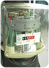
Figure 1 shows an older nonelectric heat meter I recently came across in the mechanical room of a German hotel. This device, which dates back to 1964, uses thermo-mechanical components to measure and record heat flow to a large building complex. The quantity being tallied by this meter has units of MWh (Mega-Watt-hours). In case you wondering, 1 MWh = 3,412,387 Btus.
Early electronic-based heat meters were available in the United States beginning in the 1970s. They were primarily used for performance monitoring in specialty applications, such as solar energy systems. These first-generation heat meters were not commonly specified for multitenant buildings because conventional energy was cheap and the call for energy conservation seemed like a lone voice in the wilderness. Very few American HVAC designers even knew such technology existed.
Today, state-of-the-art electronics and Web-enabled devices have elevated heat metering to a new level. With America now feeling the pinch of increasing energy prices and the commensurate need for energy conservation, it’s time to deploy this technology on a wide basis and reap the benefits long enjoyed overseas.
The Theory
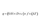
Heat metering is based on basic physics, the same physics we’ve discussed in many past columns. So here’s a quick reminder of how fluid properties, flow rate and temperature difference come together to quantify heat transfer.The rate at which a hydronic system moves sensible heat to a load can be calculated using Formula 1.
Where:
q = rate of heat flow (Btu/hr)
D = density of fluid (lb/ft3)
c = specific heat of fluid (Btu/lb/degrees F)
f = flow rate (gpm)
∆T = temperature change of fluid (degrees F)
8.01 = units conversion factor
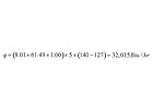
For example, a water stream at 140 degrees F enters the heating distribution system for a condominium at 5 gallons per minute (gpm). The water returns from the distribution system at 127 degrees F. What is the rate of heat release into the condo under these conditions?
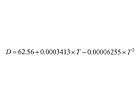
D = density of water (lb/ft3)
T = temperature of water (degrees F)
At 133.5 degrees F, the density of water is calculated to be 61.49 lb/ft3. The specific heat of water at 140 degrees F is 1.00 Btu/lb/degrees F.
Putting these numbers into Formula 2 yields these results.
From How Fast To How Much
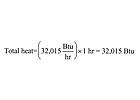
If the flow and temperature conditions of this example held constant for one hour, the amount of heat transferred to the condo would be this.
Consider Table 1, in which the time increment is reduced to one minute (e.g., 1/60 hour). The supply temperature, return temperature and flow rate are listed for each of three one-minute intervals, and are assumed to hold constant within each one-minute interval.

Modern electronics allows the measuring time increment to be very small (fractions of a second). Thus, modern heat meters can perform several calculations every minute to accurately measure total heat transfer to the load. Most heat metering systems also correct for changes in the density and specific heat of the fluid as its temperature changes.
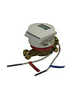
The hardware needed for heat metering always involves simultaneous measurement of flow and temperature change. This requires two accurate temperature sensors and an equally accurate flow meter. The hardware concept is shown in Figure 2.

To summarize, the task of any heat meter is taking rapid and simultaneous “snapshots” of supply temperature, return temperature and flow rate; calculating the incremental amount of heat represented by each snapshot; and adding them up.
Motivated Metering
Now that we’ve covered the basic physics, let’s look at why heat metering makes sense. The benefits are numerous and compelling. Here’s 10 to ponder.1. Heat for space heating and domestic hot water (DHW) is generated by a central boiler plant that can operate at higher efficiency than individual heat sources. This is especially true when the latter are grossly oversized for the small loads of retail shops, apartments or condo units. Producing heat at higher efficiency lowers heating costs for everyone in the building.
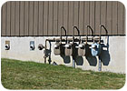
2. Using a centralized boiler plant with a single gas meter eliminates monthly charges associated with multiple gas meters (one for every unit). (See Figure 5). Higher gas usage through a single meter may reduce the cost per unit of fuel (this, of course, depends on the utility rate structure).
3. With a central mechanical room, there may be no need to install gas piping throughout a building (assuming gas-fired appliances are not used). This reduces cost and decreases the danger of accidental gas leakage and the associated fire potential.
4. A central mechanical room eliminates the need for venting a separate heat source from each unit. You know - all those little 3-inch B-vents sticking up through the roof, or all those PVC vents popping out through the walls. How ugly is that?
5. Boiler servicing and collection of heat meter data can be done (with some metering systems) without entering individual apartments, condos, etc.
6. Eliminating a boiler and DHW tank within each unit lowers the mechanical system cost per square foot of living/commercial space.
7. The floor space freed up by eliminating a boiler and DHW tank and their associated access space can reduce the mechanical system to a compact wall-mounted panel within each unit. The extra floor space can be used for other purposes that command higher value (i.e., bigger bath, bigger kitchen, more retail space, etc.).
8. Any noise associated with the heat source is confined to the mechanical room and not present within individual units.
9. The possibility of carbon monoxide leakage is limited to the central mechanical room rather than present in each unit.
10. Renters have the option of higher space temperatures if they choose but are billed accordingly. This encourages energy conservation. Some studies indicate energy use reduction of at least 20 percent based on the “user incentive” to conserve energy.
Hardware Configurations
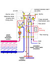
There are several ways to configure a heat metering “substation” to interface between the building mains and an apartment, condo or retail shop. The hardware used obviously depends on the type of loads served and the necessary operating temperatures and flow rates. Figure 6 shows one concept for a substation that provides space heating and instantaneous domestic hot water.Heated water, let's say at 140 degrees F, is constantly entering the common port of the diverting valve within the substation. In its default position, this valve directs the water through a small stainless-steel heat exchanger, allowing for instantaneous domestic hot water production whenever cold water is drawn through the heat exchanger. An anti-scald-rated tempering valve limits delivery temperature of the domestic hot water. This approach provides DHW on demand without need for a storage tank. The supply and return piping to the substation, diverter valve and heat exchanger are well-insulated to reduce standby heat losses.
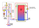
When space heating is needed (and the DHW load is satisfied), the diverter valve routes the entering hot water through a pair of closely spaced tees that supplies a mixing valve (thermostatic or motorized) to regulate supply temperature to the space-heating distribution system within the apartment, shop, etc. The circulator within the substation could be a fixed speed or a “smart pump,” depending on the type of zoning (if any) used in the distribution system.
All system water entering the substation from the supply main passes by the inlet temperature sensor. Likewise, all system water leaving the substation passes by the outlet temperature sensor. A flow meter simultaneously records flow between the mains and the substation. The temperature drop and flow rate data is processed and recorded by the heat meter within the substation.

The temperature drop across the piping connecting the substation to the mains could be significantly higher than 20 degrees F (depending on boiler supply temperature). Higher ∆Ts reduce flow requirements and, thus, keep pipe size and components within the substation relatively small. For example, with a 40-degree F temperature difference between the supply and return piping to the substation, 1/2-inch-sized tubing can easily convey 60,000 Btu/hr.
The limiting factor on supply temperature and temperature drop for this type of substation is the year-round need for domestic hot water. This precludes the option of deeply resetting the water temperature in the building mains during mild weather.
We’ve only scratched the surface of Btu metering. In my opinion, it’s a highly underutilized strategy in North America at the present time. Ironically, it’s perfect for the multiple unit buildings, both residential and commercial, now being constructed throughout North America. It addresses the concerns of developers, owners and tenants in a synergistic and mutually beneficial manner. It encourages energy conservation while also providing unsurpassed comfort heating and instantly available DHW.
It’s time for our industry to get serious with this concept and deploy it on a much wider basis. Stay tuned; you’ll be hearing more on this subject in the near future.
Links
Looking for a reprint of this article?
From high-res PDFs to custom plaques, order your copy today!


