What Difference Does It Make?
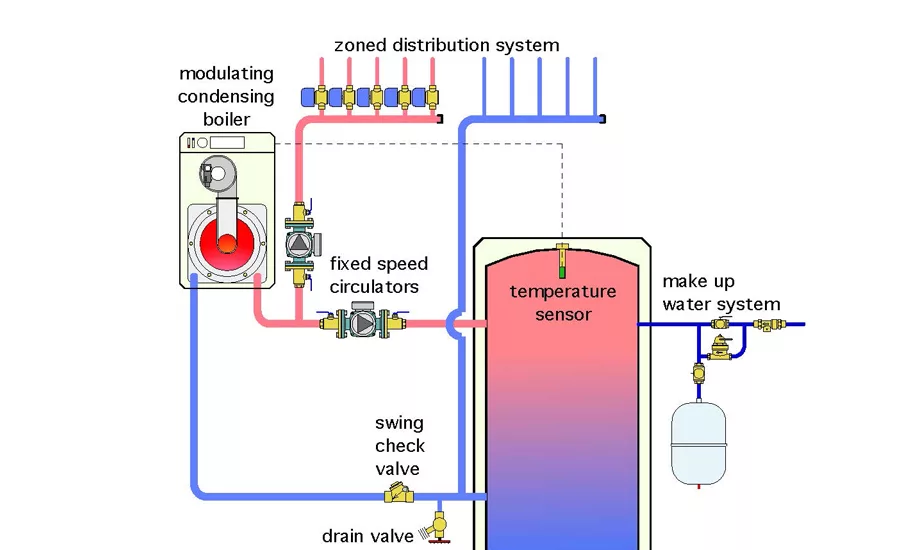
The Glitch. An installer decides to use a buffer tank between a mod/con boiler and a highly zoned distribution system. They select and install the buffer tank and other hardware as shown in figure 1.
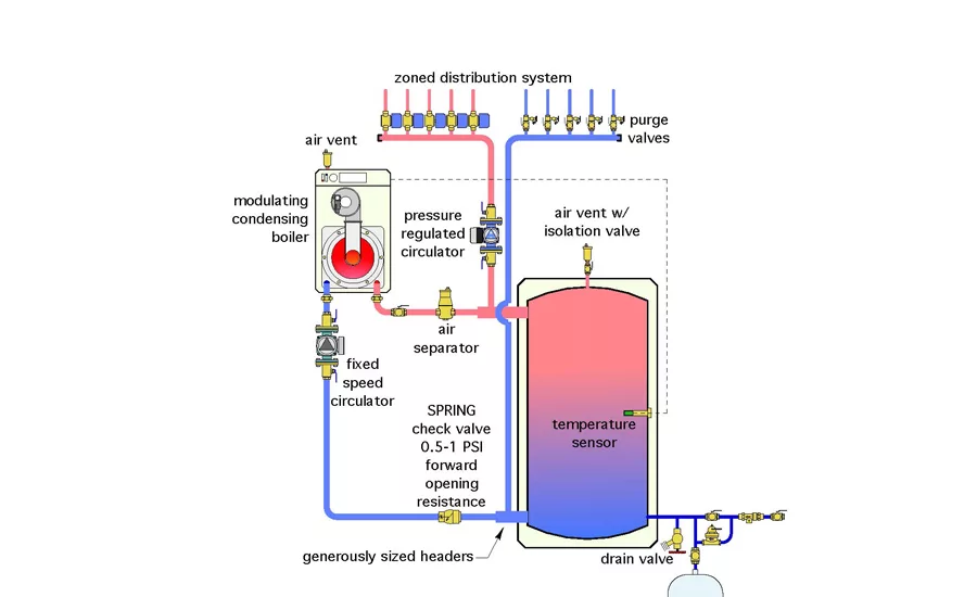
The Fix: The corrections are all shown in figure 2.
The Glitch:
An installer decides to use a buffer tank between a mod/con boiler and a highly zoned distribution system. They select and install the buffer tank and other hardware as shown in figure 1. The boiler is programmed to turn on when any zone is calling for heat, and the temperature sensor at the top of the buffer tank drops to 120 ºF. The boiler turns off when the temperature at that sensor reaches 140 ºF, or if no zone is calling for heat. The load circulator turns on whenever any zone circuit calls for heat. Can you spot several errors or omissions in the proposed system?
Here’re a dozen goof ups in the original configuration.
1. The sidewall connections on the buffer tank are located well down from the top of the tank, and well up from the bottom of the tank. This will leave the hottest and coolest water “stranded” in the tank, because the hottest water doesn’t “want” to come down from the top, and the coolest water doesn’t “want” to move up from the bottom.
2. The swing check valve in the boiler inlet pipe will not stop water returning from the load circuits from migrating through the boiler when it’s off. This unnecessarily dissipates heat through the boiler enclosure and reduces the supply water temperature to the load circuit due to mixing at the upper tank header.
3. The pipe sizes entering the sidewall connections on the tank are not increase relative to the boiler and load circuit piping. Given the common practice of sizing piping in small hydronic systems for 4 feet per second velocity, the flow velocity entering the tank will be well above the suggest 2 feet per second limit.
4. The make up water system could work as shown, but any cool water entering the tank would mix with what is likely to be hotter water, which tends to disrupt temperature stratification.
5. The temperature sensor mounted at the top of the tank will tend to reach the temperature at which the boiler turns off before the water well below the sensor has reached this temperature. It would be better to located the sensor at the mid-height of the tank.
6. The drain valve will not allow water below the lower sidewall connect to be drained from the tank.
7. The fixed speed circulator on the distribution system does not provide differential pressure control as zone valves open and close. If a fixed speed circulator is used with valve-based zoning, a differential pressure valve should be installed. Even better, use a variable speed pressure-regulated circulator and forget the bypass valve.
8. The piping between where the load circuit connects to the tank headers is longer than necessary. This will add head loss to the common piping path and decrease hydraulic separation between the circulators.
9. There are no purging valves on the return side of the zone circuits.
10. The boiler circulator should be pumping into, not away from, any mod/con boiler (or other heat source) that has a relatively high flow resistance.
11. There’s not central air separator in the system.
12. There’s no air vent to let trapped air escape from the top of the buffer tank.
The Fix:
The corrections are all shown in figure 2.
By the way, if you read April’s Hydronics Workshop column you probably identified many of the intension errors quickly. If you haven’t read that column, please do so for a more complete explanation of the glitches and the fixes.
Looking for a reprint of this article?
From high-res PDFs to custom plaques, order your copy today!


