Backward Thinking

- Can flow reversal even occur?
- Would it cause damage or interfere with other parts of the system if it did occur?
How might it affect the heat output of the secondary circuits?
- Should I use a large circulator in the primary loop to make sure flow reversal cannot occur?
The concept of flow reversal runs counterintuitive to the idea of a single primary loop supplying heat to several secondary loops. It's easy to conceptualize a primary circulator as having to produce enough flow to “feed” all the operating secondary circulators.
Fortunately, this is not true. Although the primary loop does supply heat to each secondary circuit, it does not supply flow to each secondary circuit. Supplying heat to a secondary circuit is evidenced by a drop in temperature of the primary loop flow as it passes a pair of closely spaced tees. This is entirely different from supplying flow to the secondary circuit.
In animated terms, the primary circulator doesn't even know the secondary circuits exit and vice versa. Each circulator operates as if the circuit in which it is installed is completely isolated from the other circuits.
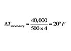
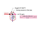
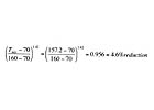
Let's look at a typical system in which a primary loop serves a secondary circuit having a design load of 40,000 Btu/hr. Assume the primary loop flow rate is 10 gpm and that the water arriving at the first tee (of the closely spaced pair of tees) is at 160 degrees F. Also assume that the circulator/piping design used for the secondary circuit allows a flow rate of 4 gpm to develop. Figure 1 shows the situation along with the calculations for temperature drops.
Following The Energy
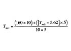
The best method for predicting the output of a situation like this where multiple energy flows converge is to simply account for all energy carried in and out of the process. Just as the flow of water into and out of a tee must balance, the energy carried into a mixing point must equal the energy carried out of that point. This concept is based on the first law of thermodynamics, which states that energy cannot be created or destroyed - only exchanged.
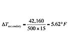
Since the secondary circuit load removes 40,000 Btu/hr. of heat, the temperature drop in the secondary circuit is:
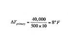
The temperature drop along the primary loop can also be determined by accounting for the fact that heat is being removed at the primary/secondary interface at a rate of 40,000 Btu/hr. Hence the temperature drop in the primary loop is:
There is simply no way around these mathematical consequences of thermodynamics, and that's a good thing. Learn it, trust it and then use it to answer many of your hydronic design questions.
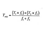
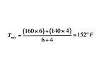
It's also possible to calculate the water temperature leaving the downstream tee by applying the “mixed-stream formula,” which again is based on conservation of thermal energy at a mixing point:
Overpumping Option
About now some of you are probably thinking, “That's all fine and dandy as long as the flow in the primary loop is higher than the flow in the secondary loop. But what happens if this is not the case?” Well, let's take a look.Suppose a circulator capable of generating a flow rate of 15 gpm was installed in the secondary circuit, and the piping was scaled up accordingly. Figure 3 illustrates the resulting flows.

Also notice that the flow rate in the primary loop for all practical purposes does not change. Why? Because the insignificant pressure drop between the closely spaced tees effectively prevents the primary loop from “feeling” any change in its hydraulic resistance. Remember, the primary loop doesn't even “know” the secondary circuit exits.
An even more interesting result is what happens to temperatures and heat transfer in the secondary circuit. Again, we have to follow the energy into and out of the tees to predict what will happen.
The flow reversal between the tees now creates a mixing point at the upstream tee. Just the opposite of what occurred in the first scenario where mixing occurred at the downstream tee.

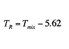
Tmix= supply temperature to the secondary circuit (degrees F)
TR = return temperature from the secondary circuit (degrees F)
Unfortunately, we don't currently know the value of the return temperature from the secondary circuit (TR), and without this, we can't calculate Tmix. We can, however, make a couple more observations that get us out of this situation.
One is that the heat output from the load will increase slightly, based on the increased flow rate through the heat emitters. For fin-tube baseboard, the increased heat transfer can be estimated as follows:
Anyway, lets conservatively assume the load is now 5.4 percent higher (42,160 Btu/hr. rather than 40,000 Btu/hr.) due to the flow rate increase. It's a conservative assumption because we already realize that the supply temperature to the load will be reduced because of mixing at the upstream tee.
The temperature drop across the secondary load is now:

Knowing this, we further recognize that the lower supply temperature also lowers heat output from the secondary circuit. How much? Here's an estimate, again assuming the heat emitters are fin-tube baseboard, and a room air temperature of 70 degrees F.
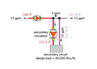
Figure 4 shows the final picture of the flow reversal situation.
So where does this leave us? Well, we've conceptually installed a larger secondary circulator and managed to reverse flow between the tees. However, for all practical purposes, we've not changed the heat output of the secondary circuit, nor have we changed the temperature of the water leaving the downstream tee. Had this scenario been installed, we would have wasted money on a larger secondary circulator as well as larger secondary piping. We would also have created a system that requires substantially more electricity to operate the larger secondary circulator for years to come. Over a typical 20-year design life, this added operating cost could approach or exceed $1,000. Is this a smart move? Not in my book. By the way, if you installed a larger primary circulator under the premise that it would prevent flow reversal, you are just wasting even more pumping energy.
We've seen that flow reversal is possible in a P/S system, but when it occurs, the heat transfer from the secondary circuit is mostly unaffected, as are the other secondary loads in the system. The only significant difference is a needless increase in both installation and operating cost for the oversized secondary circulator and piping. This is something our industry can do without. As I've stated in the past - head is a terrible thing to waste.
Links
Looking for a reprint of this article?
From high-res PDFs to custom plaques, order your copy today!


