Fast Responders
Low-mass heat emitters are essential
to the future of hydronic heating.
If our industry held a contest to determine the “best” type of hydronic heat emitter for residential applications, there is little doubt that radiant floor heating would win. During the last two decades, the market for hydronic radiant floor heating has grown by more than 1,500 percent. Both the heating trade and consumers have learned about the benefits floor heating offers. Given the wide variety of hardware now available for its implementation, some might even say that radiant floor heating is approaching a commodity status.
I have met those who feel that radiant floors are always the best solution for heating any building. If the budget for floor heating just isn’t there, other types of heat emitters such as fan-coils, panel radiators and baseboard are available, but often are viewed as a “downgrade” from floor heating.
As one who’s designed several hundreds of miles of tubing into floor heating systems, I can certainly verify that they perform great in many applications. I can also state that floor heating is not, and never has been, a one-size-fits-all solution for every space-heating need.

A dominant characteristic of slab heating is high thermal mass (e.g., the ability of the slab to store a large quantity of heat). In some situations, this mass is a godsend. One example is a garage structure in which overhead doors are often opened for several minutes in cold weather. During such conditions, heat stored in the slab is quickly delivered to the surface to compensate for the rapid increase in heating load. As soon as the doors are closed, the heat stored within the slab rapidly restores comfort.
High thermal mass can also be a detriment to intended performance. One example is the inability of a high-mass floor slab to quickly reduce its heat output when sudden and significant internal heat gains occur within the building. The slow response of a heated slab also precludes use of daily setback schedules. Although turning the thermostat down several degrees immediately stops further heat input to the slab, it doesn’t stop further release of the heat already parked in tons of concrete. The building, especially if it’s well-insulated, may only coast down a couple of degrees over a 10-hour setback period on a cold winter night. The energy-saving potential associated with regular night setback is just not there.
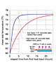
Longer-duration setbacks of several successive days are possible in buildings with heated floor slabs, but timing is everything. It can take many hours to restore normal comfort conditions in buildings where a heat slab is recovering from a deep setback condition, as illustrated in Figure 1.
These curves show the average temperature of two 2,400-square-foot concrete floor slabs vs. time, based on a steady heat input rate of 60,000 Btu/hr. Both slabs are starting from an assumed temperature of 60 degrees F. The room temperature is assumed constant at 65 degrees F. Eventually, the 6-inch slab reaches the same nominal 77-degree F average temperature as the 1.5-inch thick slab as it continues to accept heat at 60,000 Btu/hr. However, this nominal 17-degree rise in average slab temperature is going to take more than 24 hours. It’s like trying to accelerate a loaded freight train with a motorcycle engine.
 Another
classic scenario that illustrates the sluggish response of a heated slab is a
house in a cold climate with a significant window area facing south or
southeast. During a cold winter night, the floor heating system does just what
it’s supposed to do in keeping the home comfortable. By 6 a.m., the surface
temperature of the slab is probably in the lower 80s and there’s lots of heat
percolating to the floor surface.
Another
classic scenario that illustrates the sluggish response of a heated slab is a
house in a cold climate with a significant window area facing south or
southeast. During a cold winter night, the floor heating system does just what
it’s supposed to do in keeping the home comfortable. By 6 a.m., the surface
temperature of the slab is probably in the lower 80s and there’s lots of heat
percolating to the floor surface.
However, by 9 a.m. there is abundant sunlight streaming in through windows. The incoming solar radiation is more than capable of meeting the home’s heating load, and the thermostat quickly responds to increasing indoor temperature by turning off further heat input to the floor. Unfortunately, the thermostat can’t stop the heat already stored in the slab from continuing to flow into the room, at least not until the room reaches a temperature somewhere in the mid-80s.
The resulting overshoot brings discomfort, frustration, energy waste and complaints. This scenario has probably played out tens of thousands of times over the last several years, and will only get worse as heat loads decrease and houses are designed to capture more solar gains.
The slow response characteristic of a heated concrete slab floor is exacerbated by sloppy installation techniques that leave the tubing at the bottom of the slab as shown in Figure 2. Such placement greatly increases the amount of concrete that must be warmed in the process of pushing heat off the slab’s surface. The solution is simply to lift the tubing and reinforcing wire to approximately half the slab’s depth during installation.
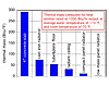
I recently made some calculations comparing the thermal mass of several hydronic heat emitters. To keep it an apples-to-apples comparison, I sized each of several heat emitters for 1,000 Btu/hr. output while operating with an average water temperature of 110 degrees F and an assumed room air temperature of 70 degrees F. The relatively low average water temperature reflects favorable operating conditions for contemporary hydronic heat sources such as condensing boilers, geothermal heat pumps and solar collectors. The graph in Figure 3 shows the results.
The low thermal mass panel radiator has less than 0.5 percent of the thermal mass of the 4-inch heated floor slab for equivalent output at the same operating conditions. It achieves this low mass by using a fin-tube element with very little water content. This type of panel can quickly warm up when necessary, such as recovery from a setback condition. Just as importantly, it can quickly stop heat output when solar energy or other internal heat gains present themselves.
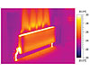
The thermographic image in Figure 4 shows the operating condition of one such panel only eight minutes after water at approximately 130 degrees F began flowing through it. For all practical purposes, this panel has achieved a steady-state condition. What appears to be flames leaping from the top of the panel is a wall surface warmed by gentle upward convective air flow through the top grill of the panel.
This type of system is simple, extremely responsive, reliable, thermally efficient, hydraulically efficient and adaptable to renewable energy heat sources. There’s plenty of stabilizing thermal mass in the combined heat source/buffer/solar storage tank, but the distribution system and heat emitters are thermally light and able to respond to fast-changing loads on a room-by-room basis. It’s an energy solution that many green-minded architects and consumers are looking for.
Figure 1.
If our industry held a contest to determine the “best” type of hydronic heat emitter for residential applications, there is little doubt that radiant floor heating would win. During the last two decades, the market for hydronic radiant floor heating has grown by more than 1,500 percent. Both the heating trade and consumers have learned about the benefits floor heating offers. Given the wide variety of hardware now available for its implementation, some might even say that radiant floor heating is approaching a commodity status.
I have met those who feel that radiant floors are always the best solution for heating any building. If the budget for floor heating just isn’t there, other types of heat emitters such as fan-coils, panel radiators and baseboard are available, but often are viewed as a “downgrade” from floor heating.
As one who’s designed several hundreds of miles of tubing into floor heating systems, I can certainly verify that they perform great in many applications. I can also state that floor heating is not, and never has been, a one-size-fits-all solution for every space-heating need.
Figure 2.
For Better Or For Worse
The classic approach to floor heating is tubing embedded in a concrete slab. This method has been used for more than a century. It’s one of the most cost-effective forms of radiant panel heating for projects where the slab, and good underslab insulation, are already planned for the building.A dominant characteristic of slab heating is high thermal mass (e.g., the ability of the slab to store a large quantity of heat). In some situations, this mass is a godsend. One example is a garage structure in which overhead doors are often opened for several minutes in cold weather. During such conditions, heat stored in the slab is quickly delivered to the surface to compensate for the rapid increase in heating load. As soon as the doors are closed, the heat stored within the slab rapidly restores comfort.
High thermal mass can also be a detriment to intended performance. One example is the inability of a high-mass floor slab to quickly reduce its heat output when sudden and significant internal heat gains occur within the building. The slow response of a heated slab also precludes use of daily setback schedules. Although turning the thermostat down several degrees immediately stops further heat input to the slab, it doesn’t stop further release of the heat already parked in tons of concrete. The building, especially if it’s well-insulated, may only coast down a couple of degrees over a 10-hour setback period on a cold winter night. The energy-saving potential associated with regular night setback is just not there.
Longer-duration setbacks of several successive days are possible in buildings with heated floor slabs, but timing is everything. It can take many hours to restore normal comfort conditions in buildings where a heat slab is recovering from a deep setback condition, as illustrated in Figure 1.
These curves show the average temperature of two 2,400-square-foot concrete floor slabs vs. time, based on a steady heat input rate of 60,000 Btu/hr. Both slabs are starting from an assumed temperature of 60 degrees F. The room temperature is assumed constant at 65 degrees F. Eventually, the 6-inch slab reaches the same nominal 77-degree F average temperature as the 1.5-inch thick slab as it continues to accept heat at 60,000 Btu/hr. However, this nominal 17-degree rise in average slab temperature is going to take more than 24 hours. It’s like trying to accelerate a loaded freight train with a motorcycle engine.
Figure 3.
However, by 9 a.m. there is abundant sunlight streaming in through windows. The incoming solar radiation is more than capable of meeting the home’s heating load, and the thermostat quickly responds to increasing indoor temperature by turning off further heat input to the floor. Unfortunately, the thermostat can’t stop the heat already stored in the slab from continuing to flow into the room, at least not until the room reaches a temperature somewhere in the mid-80s.
The resulting overshoot brings discomfort, frustration, energy waste and complaints. This scenario has probably played out tens of thousands of times over the last several years, and will only get worse as heat loads decrease and houses are designed to capture more solar gains.
The slow response characteristic of a heated concrete slab floor is exacerbated by sloppy installation techniques that leave the tubing at the bottom of the slab as shown in Figure 2. Such placement greatly increases the amount of concrete that must be warmed in the process of pushing heat off the slab’s surface. The solution is simply to lift the tubing and reinforcing wire to approximately half the slab’s depth during installation.
Figure 4.
Minutes Vs. Hours
The coming generation of low-energy-use houses, especially those that are designed for significant passive solar heat gain, will require heat emitters that respond quickly. They need to reach normal operating temperatures quickly when “turned on.” They also need to stop emitting heat quickly when “turned off.” The key to fast response is low thermal mass.I recently made some calculations comparing the thermal mass of several hydronic heat emitters. To keep it an apples-to-apples comparison, I sized each of several heat emitters for 1,000 Btu/hr. output while operating with an average water temperature of 110 degrees F and an assumed room air temperature of 70 degrees F. The relatively low average water temperature reflects favorable operating conditions for contemporary hydronic heat sources such as condensing boilers, geothermal heat pumps and solar collectors. The graph in Figure 3 shows the results.
The low thermal mass panel radiator has less than 0.5 percent of the thermal mass of the 4-inch heated floor slab for equivalent output at the same operating conditions. It achieves this low mass by using a fin-tube element with very little water content. This type of panel can quickly warm up when necessary, such as recovery from a setback condition. Just as importantly, it can quickly stop heat output when solar energy or other internal heat gains present themselves.
The thermographic image in Figure 4 shows the operating condition of one such panel only eight minutes after water at approximately 130 degrees F began flowing through it. For all practical purposes, this panel has achieved a steady-state condition. What appears to be flames leaping from the top of the panel is a wall surface warmed by gentle upward convective air flow through the top grill of the panel.
Figure 5.
Putting It Together
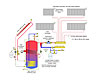
The combination of low-mass panel radiators supplied by a simple home-run distribution system powered by a variable-speed, pressure-regulated circulator is an ideal approach for the coming generation of low-energy-use houses. One example of such a system, with optional heat input from a solar collector array, is shown in Figure 5.This type of system is simple, extremely responsive, reliable, thermally efficient, hydraulically efficient and adaptable to renewable energy heat sources. There’s plenty of stabilizing thermal mass in the combined heat source/buffer/solar storage tank, but the distribution system and heat emitters are thermally light and able to respond to fast-changing loads on a room-by-room basis. It’s an energy solution that many green-minded architects and consumers are looking for.
Links
Looking for a reprint of this article?
From high-res PDFs to custom plaques, order your copy today!