Solar Appliances
If you’ve been following PM over the last year, or attended any recent trade show associated with hydronic heating, you’ve probably noticed the increased availability of hardware for solar energy systems. The solar snowball seems well on its way down the hill, and increasing consumer demand for these systems is all but certain. Our firm receives inquiries almost every day on how active solar heating can be incorporated into hydronic systems for both space heating and domestic hot water production.
Piece-By-Piece
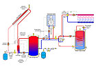
There are several “traditional” ways to set up an active solar energy system to supply space heating and DHW. Most involve separate tanks for solar storage and domestic hot water. These systems usually include a boiler for “auxiliary” heating when the solar system alone cannot supply the load. An example of such a system is shown in Figure 1.As is typical in many systems, solar energy collection is managed by a differential temperature controller that constantly monitors the temperatures at the collector array and near the bottom of the solar storage tank. Whenever the collector temperature is a set amount warmer than the tank temperature (typically 5 to 8 degrees F), the circulators on each side of the heat exchanger are turned on. When collector temperature drops to within 2 degrees F of the tank temperature, these circulators are turned off.
When there’s a call for space heating, a controller monitoring the temperature at the top of the solar storage tank makes a decision: Is the water in the solar storage tank warm enough to supply space heating? This decision could be based on a fixed setpoint temperature, or it might be based on outdoor reset control. The latter allows the lower acceptable temperature limit for the tank to drop as outdoor temperature increases. This allows extraction of solar-derived heat down to the lowest possible temperature and improves “solar yield.”
Assuming the solar storage tank is warm enough to supply space heating, the tank circulator is turned on, and hot water is delivered to the set of closely spaced tees that interface to the space-heating distribution system. These tees provide hydraulic separation between the tank circulator and the space-heating circulator.
If the storage tank is not warm enough, the tank circulator remains off, the boiler circulator turns on and the boiler fires. In this mode, the system works identically to a nonsolar hydronic system with a mod/con boiler. Even when the boiler is providing space heating, the solar storage tank temperature continues to slowly drop due to heat loss from its jacket. Assuming the tank is within heated space, this heat loss supplies a small amount of the heating load. Allowing the solar storage tank to cool down, potentially all the way to room temperature during prolonged cloudy weather, allows the collection process to begin as soon as possible when the sun reappears.
Some of you might be wondering why a three-way motorized mixing valve is used in combination with the mod/con boiler. It’s there to protect the low-temperature distribution system from the possibility of very high-temperature water in the solar storage tank during prolonged sunny weather. This mixing valve can be operated by a setpoint controller or outdoor reset controller. When the boiler is active and operating on its own outdoor reset control, the valve rotates to the fully open position and simply passes all water entering its hot port through to the distribution system.
A similar operating scheme can be set up for domestic water heating, although not based on outdoor reset control. When there’s a call for domestic water heating, the temperature of the solar storage tank is measured and, if suitably warm, the tank serves as the heat source for the indirect tank. Otherwise, the boiler goes to an elevated temperature to supply the indirect tank. Space heating could remain active during this time since the three-way mixing valve will intercede to reduce supply temperature to the radiant panel circuits. Alternatively, space heating also could be turned off to let domestic water heating operate as a priority load.
This design places two heat exchangers in the heat flow path between the solar collectors and domestic hot water - one between the collectors and solar storage tank, and the other between the solar storage tank and the domestic hot water. Each heat exchanger requires a temperature differential to drive heat across it. The smaller the heat exchanger surface area relative to the rate of heat transfer, the greater the temperature differential needed to “push” heat through it. The presence of heat exchangers between the collectors and the load raises the required operating temperature of the collectors and lowers their efficiency. The extent of this “penalty” depends on the heat exchanger sizing. Suffice it to say that generous heat exchanger sizing is important if your goal is significant solar yield.
This system also uses separate components for solar storage, domestic hot water
storage and auxiliary heating. There’s a fair amount of external piping and a
commensurate need for mechanical room space to put it all together. Like many
other hydronic system layouts, this piping arrangement could definitely benefit
from some “hardware consolidation.”
Super Tanker
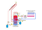
A solar energy system design concept that recently caught my attention is shown in Figure 2. Like the system of Figure 1, it provides space heating and domestic hot water using solar along with a gas-fired backup. However, it does this by merging the function of the two previous storage tanks and boiler into a single device.The tank in this system contains domestic water. An internal heat exchanger mounted near the bottom of the tank accepts heat input from the solar collectors. Due to its position, this heat exchanger is immersed in the coolest water in the tank. This allows the solar collectors to operate at the lowest possible temperature and highest possible efficiency.
Farther up the tank is a gas-fired combustion system and flue gas heat exchanger similar to what’s used on some mod/con boilers. This assembly operates when necessary to maintain a minimum acceptable DHW delivery temperature at the top of the tank. Its location in the tank allows heated water to rise upward and not disturb the cooler water at the bottom of the tank. Maintaining this temperature stratification is essential to maximizing solar gain. Some tanks even use horizontal baffles to enhance this effect.
Domestic hot water is drawn from the top of the tank and routed through an anti-scald tempering valve prior to flowing to the load. The latter is absolutely essential in any solar water heating system because the water in the tank can easily reach scalding temperatures during sustained sunny weather, especially when the DHW demand is low.
The internal heat exchanger at the top of the tank serves as a fully isolated heat source for space heating. Hot water from this coil passes through a three–way mixing valve on its way to space heating to guard against high water temperature reaching the heat emitters. Again, the combustion system fires as necessary to ensure this tank can continue to supply space heating whenever it’s needed.
Although not essential to the solar aspect of the system, the space-heating distribution system shown uses an ECM-based pressured regulated circulator to automatically adapt to the changing flow requirements as the manifold actuators open and close. Why not combine the most energy-efficient circulator technology with state-of-the-art solar heating?
The volume of hot water at the top of the tank provides a buffering effect for space heat delivery and, thus, minimizes burner cycling. This is especially important when the distribution system is divided into many small, individually controlled loads.
In this design, the solar-derived heat used for domestic hot water production
passes through a single heat exchanger (at the bottom of the tank). However,
solar-derived heat used for space heating must pass through two heat
exchangers. Design choices that reduce the operating temperature of the
space-heating distribution system will improve solar yield. Low-temperature
radiant panel heating would be a good choice.

Anti-Antifreeze Option
The systems in Figures 1 and 2 both use closed-loop solar collector circuits filled with a propylene glycol antifreeze solution. This method of freeze protection is a reliable performer, but the use of glycol always brings with it the need for fluid maintenance. This is especially true in solar energy systems, which occasionally experience high collector stagnation temperatures (think 350 degrees F+ in the collectors). These temperatures can quickly “sour” the glycol solution into a corrosive brew. If you’re not willing to acknowledge the need for glycol maintenance, or prepared to follow through with it, it’s best to find another method of freeze-protecting your solar systems.The “best” method of freeze-protecting solar collectors has been, and continues to be, a passionately debated subject among system designers and manufacturers. The most popular alternative to glycol-based collector circuits is a drainback system. In this approach, water circulates through the collectors whenever there’s heat to be gathered. When the collector circulator turns off, this water rapidly drains from the collectors and exposed piping back to the insulated storage tank. It’s crucial that all piping be properly pitched to ensure rapid and complete drainage.
Drainback systems eliminate the heat exchanger between the solar collector array and storage tank. This reduces cost and does away with the previously discussed performance penalty associated with the heat exchanger.
Some drainback systems are designed as pressurized closed-loops with captive air volumes. In this case, the water that passes through the collectors also flows through the space-heating distribution system. When properly designed, these systems work great. I’ve had this type of system working in my house for about 28 years. It’s been through several excursions to -30 degrees F and is still ticking along nicely.
Drainback systems also can be designed around a nonpressurized (atmospherically
vented) storage tank. Heat exchangers are required to transfer heat from the
unpressurized water in the solar storage tank to the pressurized space-heating
distribution system or pressurized domestic water.
Combo No. 2
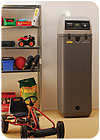
So, if you like what you’ve just read about drainback systems, but you also like the single tank/integral burner concept shown in Figure 2, take a look at Figure 3. This product is built by Rotex Heating Systems GmbH in Germany. It also provides space heating and domestic hot water through a combination of solar and gas-fired auxiliary heating, but uses drainback freeze protection for the collectors.A classic example of European industrial design, this product has the appearance of a modern appliance, a look that understates the sophisticated collection of hardware it really is. It consolidates almost all the necessary piping and combustion components within an aesthetically thought-out enclosure and, with the exception of condensate drainage, presents all piping, fuel and electrical connections to the top. A digital display provides a user interface to all control operations.
If you want to check this product out in more detail, go to the following Web site for a downloadable user manual (in English): www.rotex-heating.com/englisch/allgemein_engl/technunterl_pdf.html.
Keeping pace with the growing demand for residential solar energy systems in North America will require systems that provide turn-key installation. These systems must convey themselves to the average homeowner as an appliance, rather than a collection of experimental hardware that NASA engineers tinker with while the space shuttle is up in orbit.
We’re already seeing efforts in this direction with the numerous solar circulation stations now available in North America. I hope the expanding solar energy industry will continue this trend with completely pre-engineered plug-and-play systems. This will grease the skids for heating professionals, especially those already dealing with hydronics, to quickly and easily add a solar energy option to their offerings, and get results that work the first time.
Links
Looking for a reprint of this article?
From high-res PDFs to custom plaques, order your copy today!