Terminology Tune-Up
John Siegenthaler, PE
Over the years, I’ve heard terms used in our industry that don’t accurately portray a concept or device. I confess to using some of these terms myself, usually before I understood exactly what they meant, or considered what they might imply. I’m sure most of you hear the terminology we’re about to discuss on a daily basis. Many of you can even hold a reasonably clear peer-to-peer conversation using this terminology because it’s been around the industry for decades.
Still, imagine what these expressions might mean to hydronics novices, or potential clients listening to a description of a hydronic heating system. In my opinion, some of these terms send the wrong message about what a hydronic system does or is capable of doing. This can lead to installations that are doomed to failure.
Here is a list of expressions that I feel should be dropped in favor of more accurate verbiage.
“Radiant tubing” suggests that the tubing we install in floors, walls and ceilings transfers heat to surrounding materials primarily by thermal radiation. For most installations, this is simply not true. Heat moves from the tubing to surrounding solid materials by conduction. Radiant heat transfer occurs only when the tubing is partially or totally surrounded by cooler surfaces with air gaps or a vacuum in between. In most cases, radiant heat transfer from the tubing plays a very minor role in getting heat to the surface of the radiant panel.
I’m convinced this term has built a false confidence among some installers, who simply string “radiant tubing” through floor framing convinced it will miraculously beam out ample heat to produce toasty floors above. Many have discovered the hard way this isn’t true.
There’s nothing magical about this tubing that makes it “glow in the dark” or otherwise exude large amounts of radiant energy to surrounding materials. Why don’t we just call it what it is: PEX, PEX-AL-PEX, or rubber tubing?
Head is the total mechanical energy contained by the fluid at a point in the system. Bernoulli’s equation (Formula 1) precisely defines this total head energy.

Formula 1
Where:HT = total head energy the fluid contains (feet)
P = pressure of the fluid (psi)
D = density of the fluid (lb/ft3)
v = velocity of the fluid (ft/sec)
Z = elevation of the fluid above some reference elevation (feet)
144 and 64.4 = constants needs to make all units consistent
Since ft•lb is a unit of energy, it can be converted to any other unit of energy. For example: 777.65 ft•lb = 1 Btu. Thus, if we chose to, we could express head energy as Btu/lb or even kilowatthours/lb. It’s just that “feet” have been the customary units used for head energy for decades.
We use circulators to convert electrical energy into head energy. Because they’re not 100 percent efficient, they convert some of the electrical energy supplied to them into head, and the remainder into heat. The wire-to-water efficiency of a circulator is simply the ratio of the head energy it imparts to the water divided by the requisite electrical energy supplied to the motor.
So where does pressure come into this discussion? Use the following concept as a way to explain head and pressure.
The evidence that head energy has been added to a fluid as it passes through a circulator is an increase in pressure. The evidence that head energy has been removed from a fluid as it flows through a device is a decrease in pressure.
The increase or decrease in pressure associated with adding or removing head energy from a fluid can be calculated using Formula 2.

Formula 2
Where:H = head added or removed (feet of head)
∆P = differential pressure (psi)
144 = a constant needed based on the units used
D = density of fluid (lb/ft3)

Although there is such a thing as lightweight concrete, it’s definitely not the same as poured gypsum underlayment. The latter has been successfully used for years in many floor heating systems. The former is something that should never be used for such applications due to its low thermal conductivity.
My February 1999 PM column discussed the differences in these materials and showed why true lightweight concrete is not a good choice for floor heating applications (visit the PM archives at www.pmmag.com/CDA/Archives; free site registration required to view archives.). A graph borrowed from that column is shown in Figure 1. Notice how the floor surface temperature curve moves downward (indicating reduced heat output) as the density of the lightweight concrete used for the slab decreases. The lighter the concrete, the lower its thermal conductivity, and the poorer the slab performs.
Use of lightweight concrete for a heated floor slab can be a thermal disaster. If you hear someone suggesting such a use, be sure to tell him the resulting system will be light in weight and very light in performance.
It’s hard to imagine a less effective way of installing tubing when the intent is to warm the upper surface of the floor. The thermal resistance between the water in the tube to the top surface of the floor in Figure 1 is probably akin to covering a cast-iron radiator with a 12-inch thick fiberglass batt! Most people understand the extreme thermal consequences of the latter. Those that don’t must be the ones out there stapling tubing to floor joists.
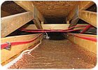
I think our industry needs to be more specific in describing how tubing integrates into the floor system. How about “underfloor tube and plate” to describe systems using both tube and plates, and “plateless staple-up” to describe installations without plates? Maybe the term “plateless” is a bit too dubious to those of you who promote this installation method. If you don’t like it, consider “naked tube staple-up” as an alternative.
However, it’s water, not gravity, that’s flowing. I suggest “buoyancy-induced flow” or “thermosyphoning” as better descriptors of what’s happening.
Why confuse people with trade lingo? I suggest we use “diverter tee system” as a replacement for one-pipe system. After all, diverter tees are what distinguishes “one pipe” systems from other types of piping layouts.
Modern hydronic systems are not limited to “boilers” as heat sources. Options include heat pumps, solar collectors, wood-fired outdoor furnaces, storage tanks heated with off-peak electricity, waste heat recovery and more. The term “hydronic heat source” is simply a more inclusive term than boiler.
I know it’s a stretch to think our industry will someday use the term “hydronic heat source” as a replacement for “boiler,” and I guarantee you’ll see the word boiler in many of my future PM columns. I’m parsing the word simply as a reminder of what trade lingo could mean to novices and potential clients. Accurate and consistent terminology improves your ability to communicate. It also helps future hydronic professionals grasp fundamentals that improve the systems they design and install.
Tell it like it is.
Links
Looking for a reprint of this article?
From high-res PDFs to custom plaques, order your copy today!