Equivalent Thinking
John Siegenthaler, PE
Most methods for estimating head loss treat fittings and valves as “equivalent lengths” of tubing having the same size as the fitting or valve. Table 1 gives equivalent lengths of some common fittings and valves.
For example, a 3/4-inch, 90-degree copper elbow has an equivalent length of 2 ft. of 3/4-inch copper tube. A 3/4-inch copper tee with flow making a 90-degree turn has an equivalent length of 3 ft. Although both fittings accomplish the same thing - turning the flow by 90 degrees - the tee has the greater equivalent length because of its sharp corner vs. the sweeping turn through the elbow.
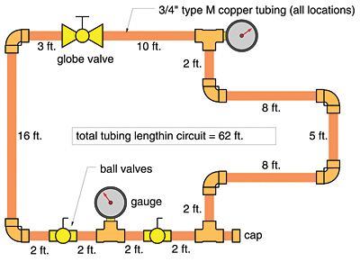
Consider the circuit shown in Figure 1. Its total equivalent length is found by adding the lengths of tubing to the equivalent lengths of the fittings and valves as follows:
- 3/4-inch tubing: 62 ft.
6, 3/4-inch x 90-degree elbows: 12 ft.
2, 3/4-inch side port tee: 6 ft.
1, 3/4-inch straight tee: 0.4 ft.
1, 3/4-inch globe valve: 20 ft.
2, 3/4-inch ball valves: 4.4 ft.
Total Equivalent Length: 104.8 ft.
What About Other Devices?
Most hydronic circuits contain components that are not listed in Table 1. Examples include boilers, panel radiators, air separators and heat exchangers. Some of these devices may create significant head loss and thus affect the flow and heat delivery capacity of the circuit. This head loss should be accounted for during design, and this calls for a visit to the math department.Formula 1 can be used for estimating the head loss of circuits built with smooth tubing, such as copper, PEX or PEX-AL-PEX.
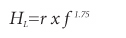
HL = head loss (in feet of head)
r = hydraulic resistance of the circuit
f = flow rate through circuit (in gpm)
1.75 = the exponent (not multiplier) of flow rate
where:
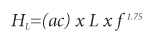
HL = head loss (in feet of head)
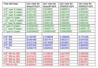
(ac) = a value accounting for tube type, size, system fluid and operating temperature (see Table 2)
L = total equivalent length of the circuit (in feet)
f = flow rate through circuit (in gpm)
1.75 = the exponent (not multiplier) of flow rate

Here's an example: Determine the head loss of a 3/4-inch copper tube circuit having a total equivalent length of 243 ft., operating at 4.5 gpm flow, and a supply water temperature of 120 degrees F. Assume a 20-degree temperature drop for the circuit.
The average water temperature in this circuit is about 120-20/2 = 110 degrees F. This is close to the 105-degree-F average temperature used in the second column of the table; therefore, the value of (ac) selected is 0.003185. A mathematical purest might interpolate between the (ac) values in the 105-degree-F and 140-degree-F columns to get a more precise value for water at 110 degrees F, but the difference is insignificant considering the entire calculation is only an estimate.
The head loss of the circuit is now estimated using Formula 2:
HL = (ac) x f1.75 = (0.003185) x 243 x (4.5)1.75=10.76 ft.
Reversing The Math
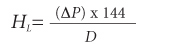
If we can treat fittings and valves as equivalent lengths of tubing, why not other components? It's just a matter of finding their equivalent lengths.Here's where a little algebra comes in handy. If we know at least one flow rate and the associated pressure drop for a component, we can get the head loss using Formula 3:
-
HL = head loss (in feet of head)
∆P = pressure drop (in psi)
D = density of fluid being used (in lb/ft3)

Remember that this equivalent length is for a specific fluid and operating temperature, as well as for a specific tube size (the same tube size for which the (ac) value is selected).

Equivalency
Here are a couple examples of how to use the above information.
The technical literature for a small wall convector lists its head loss at 5.81 ft. when operating with a water flow rate of 2 gpm. The manufacturer doesn't indicate the water temperature at which this rating was determined. Considering that fan coils usually operate at higher water temperatures, we'll assume data for 140-degree-F water. The convector has 1/2-inch piping connections, so we'll calculate an equivalent length of 1/2-inch copper tubing. The value of (ac) for 1/2-inch copper and 140-degree-F water (from Table 2) is 0.015876. Putting these numbers into Formula 4 yields Formula 4a.
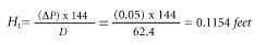
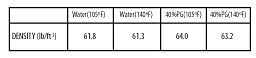
Here's another example: An air separator for 1 1/4-inch piping has a listed pressure drop of 0.05 psi at 10-gpm water flow. The testing was done with cold water having a density of 62.4 lb/ft3. The air separator will be used in a system with an average operating water temperature of 140 degrees F. Find the equivalent length of the air separator for this situation.
First, we need to convert the stated pressure drop to head loss using Formula 3 (resulting in Formula 3a).

Putting these numbers into Formula 4 yields the equivalent length (Formula 4b).
In this application, the air separator has an equivalent length of 6.3 feet of 1 1/4-inch copper tubing. This is a relatively low equivalent length consistent with the minimal pressure drop, characteristics of most inline air separators.
Now that you have a method for determining equivalent length of components, you can include these equivalent lengths into the total equivalent length of the circuit being analyzed. These lengths can be used in manual calculations, as well as software-based methods, for determining the system curve of a circuit. This is a powerful design concept, one that can help you spot flow bottlenecks before they occur, as well as correctly size circulators.
Show Us The Numbers
I've often found that flow vs. pressure drop data for many hydronic components sold in the United States is not published. Upon calling some manufacturers in search of it, I'm told this data is simply not available. By contrast, technical literature for European-built hydronic hardware almost always includes this hydraulic performance data.The lack of such data leaves conscientious designers in a quandary. Most want to properly size circulators, but without proper data they are left to “guestimate” the flow resistance of major components in their systems. Guessing too low could obviously lead to problems, so most err on the safe side by selecting circulators that are, in all probability, significantly oversized. This increases installation cost and can add hundreds of dollars to life- cycle operating cost.
To encourage better design, I urge manufacturers to test their hydronic components for the relationship between flow rate and pressure drop, and then publish this data in print and on their Web sites. Our industry has reached a point where software-based design tools can do the number crunching in a blink if only the right data can be input. Modern hydronic systems should be as “hydraulically efficient” as they are thermally efficient, and we deal with systems every week where this is not happening.
Manufacturers who provide hydraulic performance data help ensure good installations for their products. Good installations lead to repeat business and continued industry growth. In short, it's a win-win situation, so help us out here, guys ...
* Additional data on fluid properties can be determined using the Fluid Properties Calculator module in the Hydronics Design Studio software. Visit www.hydronicpros.com to download a free demo.
Looking for a reprint of this article?
From high-res PDFs to custom plaques, order your copy today!